
Method for manufacturing electrode material and electrode material

Active Publication Date: 2017-10-05
MEIDENSHA ELECTRIC MFG CO LTD
View PDF1 Cites 0 Cited by
  • Summary
  • Abstract
  • Description
  • Claims
  • Application Information

AI Technical Summary

Benefits of technology

The present invention provides an electrode material with better withstand voltage and current-interrupting capabilities than conventional materials. The invention also improves the filling rate of a porous material with highly conductive metals when produced by infiltration method. These improvements contribute to the overall performance of the electrode material.

Problems solved by technology

In infiltration method, molding of a porous material is performed by metallic molding or the like, for example; however, when increasing a molding pressure in order to improve the filling rate of the porous material, a mold gets conspicuously worn out so as to be possibly shortened in life.

Method used

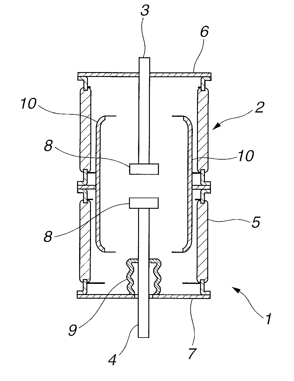

Image

  • Method for manufacturing  electrode material and electrode material
  • Method for manufacturing  electrode material and electrode material
  • Method for manufacturing  electrode material and electrode material

Examples


example 1

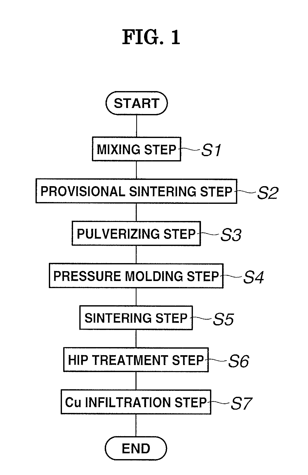
[0049]Referring now to a concrete example, a method for producing an electrode material and an electrode material according to an embodiment of the present invention will be discussed in details. An electrode material of Example 1 is an electrode material produced according to the flow chart as shown in FIG. 1.

[0050]A Mo powder and a Cr powder were sufficiently uniformly mixed at a weight ratio of Mo:Cr=9:1 as a mixing ratio by using a V type blender.

[0051]As the Mo powder, a powder having a particle diameter of 0.8 to 6.0 μm was employed. As the result of measuring the particle diameter distribution of this Mo powder by using a laser diffraction particle size analyzer, it was confirmed to have a median diameter d50 of 5.1 μm (and d10 of 3.1 μm and d90 of 8.8 μm). The Cr powder was a powder of −325 mesh (mesh opening of 45 μm).

[0052]After the mixing operation was completed, the mixed powder containing the Mo powder and the Cr powder was moved into an alumina container, followed by c...

reference example 1

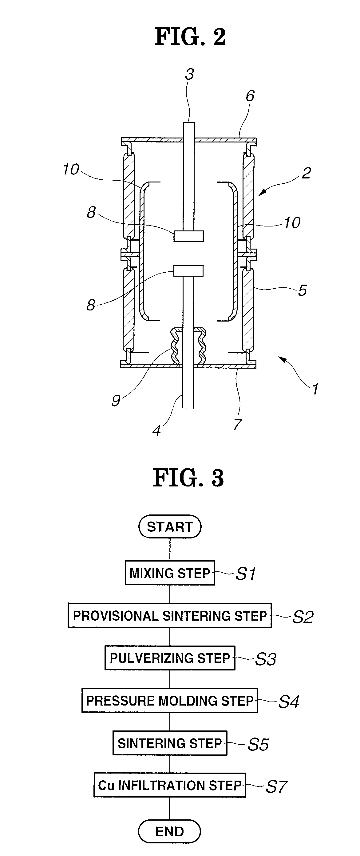
[0062]An electrode material of Reference Example 1 is an electrode material produced by the same procedure as that of Example 1 with the exception that the HIP treatment is not performed. The electrode material of Reference Example 1 is an electrode material produced according to the flow chart as shown in FIG. 3. In the flow chart as shown in FIG. 3, steps common with Example 1 are given the same reference numeral; therefore, specific explanations on such steps are omitted.

[0063]A Mo powder and a Cr powder were mixed at a weight ratio of Mo:Cr=9:1. A mixed powder was provisionally sintered, and an obtained Mo—Cr solid solution was pulverized. Pressure molding was conducted to a powder obtained by pulverizing the Mo—Cr solid solution under a pressing pressure of 2.3 ton / cm2 to obtain a molded body having a diameter of 60 mm and a height of 10 mm. This molded body was subjected to a heat treatment in a vacuum atmosphere at 1150° C. for 1.5 hours, thereby producing a sintered body. A ...

example 2

[0064]An electrode material of Example 2 is an electrode material produced by the same procedure as that of Example 1 with the exception that the pressure applied in the pressure molding step S4 is modified.

[0065]As shown in FIG. 1, a Mo powder and a Cr powder were mixed at a weight ratio of Mo:Cr=9:1. A mixed powder was provisionally sintered, and an obtained Mo—Cr solid solution was pulverized. Pressure molding was conducted to a powder obtained by pulverizing the Mo—Cr solid solution under a pressing pressure of 3.5 ton / cm2 to obtain a molded body having a diameter of 60 mm and a height of 10 mm. This molded body was subjected to a heat treatment in a vacuum atmosphere at 1150° C. for 1.5 hours, thereby producing a sintered body. A filling rate of the sintered body was 54.9%. On this sintered body, a HIP treatment was performed at 1050° C., 70 MPa for 2 hours. A filling rate after the HIP treatment was 68.6%. The HIP-treated body was then infiltrated with Cu to serve as the elect...


PUM

PropertyMeasurementUnit
Fractionaaaaaaaaaa
Temperatureaaaaaaaaaa
Electrical resistanceaaaaaaaaaa

Abstract

What is disclosed is an electrode material including a sintered body containing a heat resistant element and Cr and being infiltrated with a highly conductive material. A powder mixture of a heat resistant element powder and a Cr powder is subjected to a provisional sintering in advance, thereby causing solid phase diffusion of the heat resistant element and Cr. After a Mo—Cr solid solution obtained by the provisional sintering is pulverized, the pulverized Mo—Cr solid solution powder is molded and sintered. A sintered body obtained by sintering is subjected to a HIP treatment. The highly conductive metal is disposed on the sintered body after the HIP treatment, and infiltrated into the sintered body by heating at a predetermined temperature. By conducting the HIP treatment, the withstand voltage capability and current-interrupting capability of the electrode material are improved.

Description

TECHNICAL FIELD[0001]The present invention relates to a technique for controlling composition of an electrode material.BACKGROUND OF THE INVENTION[0002]An electrode material used for an electrode of a vacuum interrupter (VI) etc. is required to fulfill the properties of: (1) a great current-interrupting capacity; (2) a high withstand voltage capability; (3) a low contact resistance; (4) a good welding resistance; (5) a lower consumption of a contact point; (6) a small interrupting current; (7) an excellent workability; (8) a great mechanical strength; and the like.[0003]A copper (Cu)-chromium (Cr) electrode has the properties of a good current-interrupting capacity, a high withstand voltage capability, a good welding resistance and the like and has widely been used as a material for a contact point of a vacuum interrupter. The Cu—Cr electrode has been reported that Cr particles having a finer particle diameter are more advantageous in terms of the current-interrupting capacity and t...

Claims


Application Information

Patent Timeline
IPC IPC(8): B22F3/26B22F9/04H01H1/02C22C1/04C22C1/08B22F3/15C22C27/04
CPCB22F3/26B22F3/15B22F9/04H01H1/0206C22C1/045C22C1/08C22C27/04C22C9/00B22F7/008B22F7/06C22C1/0458C22C1/0475B22F2998/10B22F3/10B22F3/02C22C27/06
Inventor ISHIKAWA, KEITAKITAKIZAKI, KAORUHAYASHI, SHOTA
Owner MEIDENSHA ELECTRIC MFG CO LTD
Learn More