Electrostatic chuck and method of manufacturing electrostatic chuck
a technology of electrostatic chuck and electrostatic chuck, which is applied in the direction of electrostatic holding device, hot plate heating arrangement, plant cultivation, etc., can solve the problems of low heat dissipation from the substrate, the chuck is increasingly exposed to high-temperature environments, etc., and achieves higher thermal conductivity and higher thermal conductivity
Inactive Publication Date: 2006-09-28
NGK INSULATORS LTD
View PDF7 Cites 22 Cited by
- Summary
- Abstract
- Description
- Claims
- Application Information
AI Technical Summary
Benefits of technology
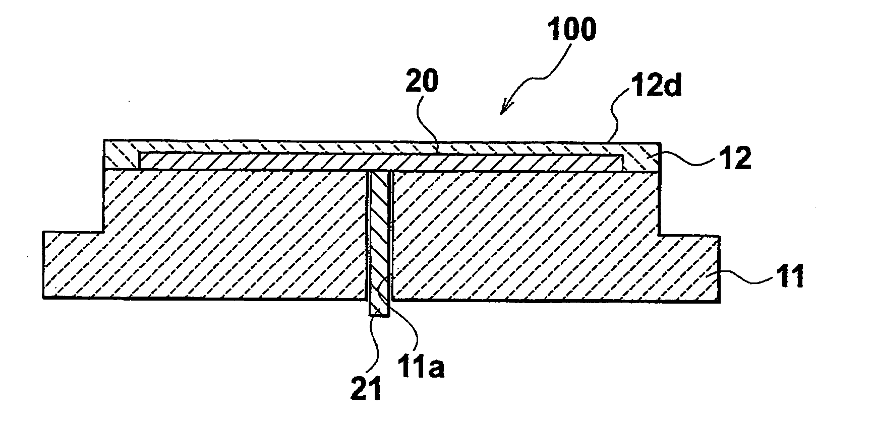
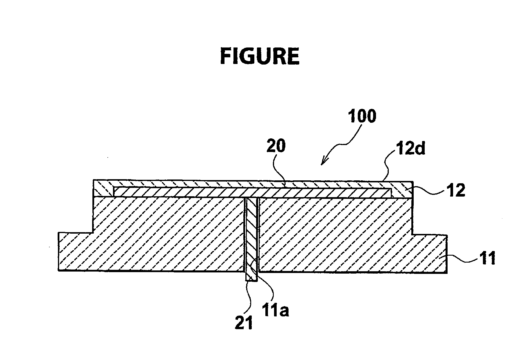
[0009] A first aspect of the present invention is to provide an electrostatic chuck, including, a base plate made of ceramic, an electrode for generating an electrostatic clamping force, and a dielectric material layer formed on the electrode. The dielectric material layer is made of ceramic having a volume resistivity of not less than 1×10¹⁵ Ω·cm at 100° C. and the same main constituent as the base plate, wherein the base plate has a higher thermal conductivity than the dielectric material layer.
[00...
Problems solved by technology
However, recently, electrostatic chucks used in semiconductor manufacturing equipment tend to be increasingly exposed to high-temperature environments.
Thus, there has been the problem that when alumina is used as a material for a base plate, its heat dissipation from a substrate is low.
Method used
View moreImage
Smart ImageViewing Examples

Examples
examples
[0054] Next, the present invention will be described in more detail using examples. However, the present invention is not limited to the following examples at all.
(Electrostatic Chuck)
Login to View More PUM
 Abstract
An electrostatic chuck includes, a base plate made of ceramic, an electrode for generating an electrostatic clamping force, and a dielectric material layer formed on the electrode and made of ceramic having a volume resistivity of not less than 1×10¹⁵ Ω·cm at 100° C. and the same main constituent as the base plate. The base plate has a higher thermal conductivity than the dielectric material layer.
Description
CROSS REFERENCE TO RELATED APPLICATIONS [0001] This application is based upon and claims the benefit of priority from prior Japanese Patent Application P2005-087081 filed on Mar. 24, 2005; the entire contents of which are incorporated by reference herein. BACKGROUND OF THE INVENTION [0002] 1. Field of the Invention [0003] The present invention relates to an electrostatic chuck and a method of manufacturing the same. [0004] 2. Description of the Related Art [0005] Heretofore, in semiconductor manufacturing processes and liquid crystal manufacturing processes, an electrostatic chuck is used which adsorbs and holds a semiconductor substrate or a glass substrate. Electrostatic chucks adsorb a substrate using Coulomb force or Johnson-Rahbek force. The Coulomb force is an electrostatic clamping force generated between a substrate placed on the surface of a dielectric material layer of the electrostatic chuck and an electrode of the electrostatic chuck. In the electrostatic chuck which ads...
Claims
Login to View More Application Information
Patent Timeline
 IPC IPC(8): H05B3/68
CPCH01L21/6833H02N13/00H05B3/143B26D1/15B26D7/06B26D7/2614A01G18/40
Inventor MATSUDA, HIROTONOBORI, KAZUHIROIMAI, YASUYOSHIKAWAJIRI, TETSUYA
Owner NGK INSULATORS LTD
Features
- Generate Ideas
- Intellectual Property
- Life Sciences
- Materials
- Tech Scout
- Unparalleled Data Quality
- Higher Quality Content
- 60% Fewer Hallucinations
Learn More Browse by: Latest US Patents, China's latest patents, Technical Efficacy Thesaurus, Application Domain, Technology Topic, Popular Technical Reports.
© 2025 PatSnap. All rights reserved.Legal|Privacy policy|Modern Slavery Act Transparency Statement|Sitemap|About US| Contact US: help@patsnap.com