Barcode reading apparatus and method therefor

a barcode and scanner technology, applied in the field of barcode reading mechanism of dna microarray scanner, can solve the problems of weak signals and increased problems, and achieve the effect of strong identifying signals

Inactive Publication Date: 2006-09-28
AGILENT TECH INC
View PDF14 Cites 41 Cited by
  • Summary
  • Abstract
  • Description
  • Claims
  • Application Information

AI Technical Summary

Benefits of technology

[0008] In one aspect, the present invention provides a barcode reading apparatus for reading a translucent barcode label that has opaque indicia such as spaced black bars on a translucent background. The barcode reading apparatus includes a transmitter for projecting an incident light beam toward the label so that some of the light is returned back from the translucent background toward a detector portion of a barcode reader and some of the light passes through the translucent background to a light returning device on the opposite side of the slide, said light returning device bearing a light returning surface. The term “light returning device” is used herein to describe a device bearing a light returning surface. A light returning surface is a surface that is capable of receiving a beam of light from a source, and, in reaction to receiving the beam of light, radiates a return beam of light toward a light sensor associated with the source. The portion of the incident light beam that strikes the light returning surface is returned back through the slide toward the detector portion of the barcode reader. This portion of returned light produces a signal that is added to the signal produced by the portion of the incident light beam initially returned from the translucent background of the barcode label to produce a much stronger identifying signal.

Problems solved by technology

In many cases the signals are not strong enough to provide an accurate identification of the barcode being read.
This problem becomes more acute if there is any degradation of the label during treatment of the slide during the steps in pre and post hybridization operation, i.e. washings.

Method used


Image

  • Barcode reading apparatus and method therefor
  • Barcode reading apparatus and method therefor
  • Barcode reading apparatus and method therefor

Examples


Embodiment Construction

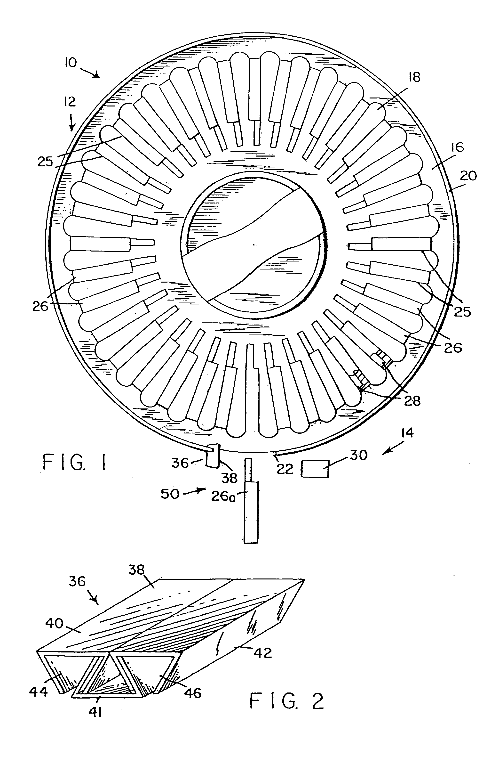
[0015] Referring to FIGS. 1 and 2, the scanning mechanism of the present invention is generally indicated by the reference numeral 10 and includes a slide carousel, generally indicated by the reference numeral 12, and a barcode reading apparatus, generally indicated by the reference numeral 14. The slide carousel 12 includes a fixed base 16 and a slide tray 18 rotatably mounted on the base 16. The base 16 has an annular outer wall 20 that includes a front opening 22. The tray 18 has slots 25 for holding a plurality of slide holders 26. Each slide holder 26 contains a slide 28.

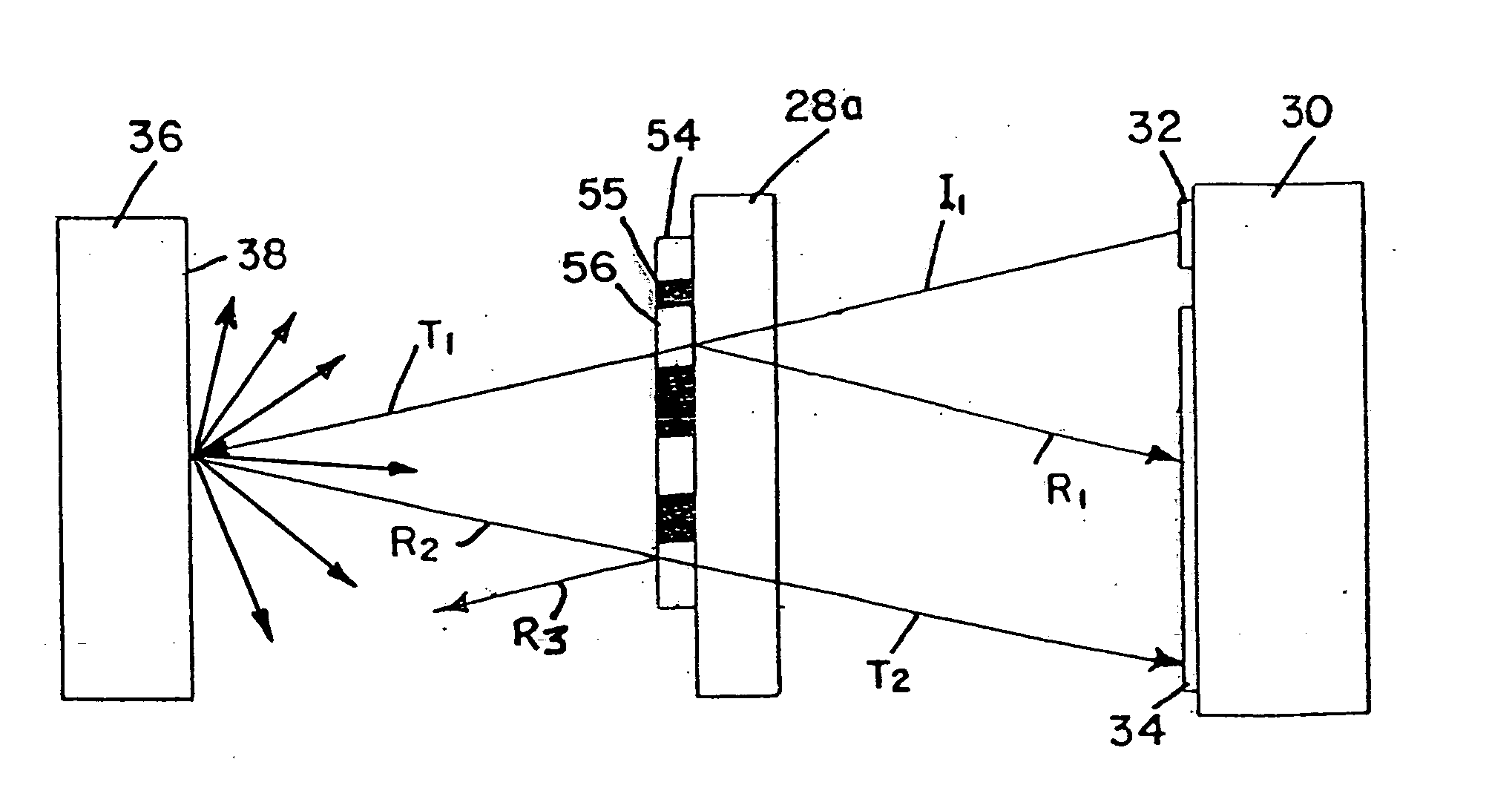
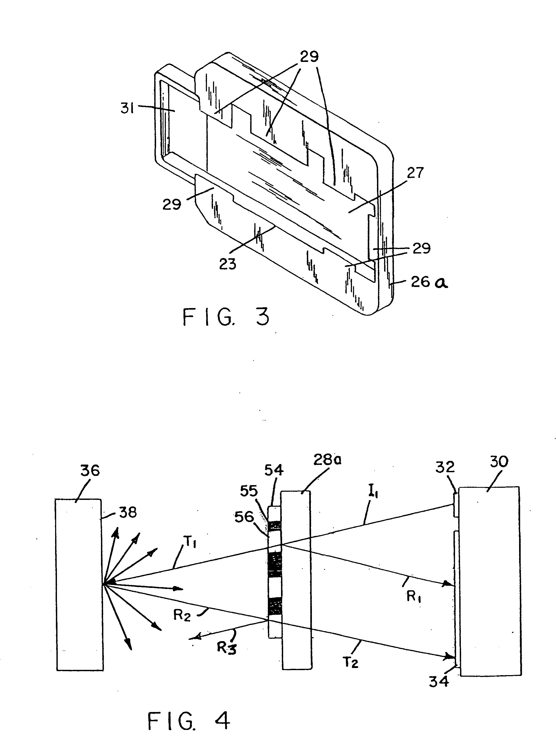
[0016] Referring to FIG. 3, one of the slide holders 26 is shown without its slide. Slide holder 26 defines a cavity 23 for receiving the slide. The slide is held in place by a side wall 27 and tabs 29. Side wall 27 can be pivoted to enable the slide to be inserted and then locked in place. Cavity 23 has a portion that extends beyond side wall 27 to form a window 31. The barcode label on the slide is positione...


PUM


Abstract

A barcode reading apparatus for reading a translucent barcode label or strip that has opaque indicia such as spaced black bars on a translucent background. The barcode reading apparatus includes a transmitter for projecting an incident light beam toward the label so that some of the light is returned back from the translucent background and some of the light passes through the translucent background to a light returning surface on the opposite side of the slide. The portion of the incident light beam that strikes the light returning surface is returned back through the slide toward a detector portion of the barcode reader. This portion of returned light produces a signal that is added to the signal produced by the portion of the incident light beam initially returned from the translucent background of the barcode label to produce a much stronger identifying signal.

Description

CROSS-REFERENCE TO RELATED APPLICATIONS [0001] NOT APPLICABLE BACKGROUND OF THE INVENTION [0002] The present invention relates generally to a scanning mechanism and, more specifically, to a barcode reading mechanism for a DNA Microarray Scanner that identifies and quantifies genetic material. [0003] A microarray scanner includes a carousel that has radial slots. The carousel is rotatably mounted on a support that includes an annular wall surrounding the carousel. The annular wall has an access opening to the carousel. Each radial slot is adapted to receive a holder containing a transparent slide, e.g. a 1″ by 3″ glass slide. Each slide is located in a custom slide holder. A biological sample to be examined is located on one side of the slide. The sample is DNA or RNA material extracted from a biological sample. In a process known as Hybridization, the sample is allowed to bond with known DNA sequences or probes deposited in a two-dimensional array on the glass slide. A barcode that ...

Claims


Application Information

Patent Timeline
Patent Type & Authority Applications(United States)
IPC IPC(8): G06K7/10
CPCG06K7/10683G06K19/06046
Inventor FAIZ, TARIQ NADEEMAMEER, JAVED
Owner AGILENT TECH INC
Why Eureka
Try Eureka