
Missile ejection system and launching canister thereof

a technology of missile ejection and canister, which is applied in the direction of weapons, weapons, transportation and packaging, etc., can solve the problems of ground equipment or peripheral missiles in the launcher being damaged, and causing thrust loss

Active Publication Date: 2006-09-28
AGENCY FOR DEFENSE DEV
View PDF11 Cites 24 Cited by
  • Summary
  • Abstract
  • Description
  • Claims
  • Application Information

AI Technical Summary

Benefits of technology

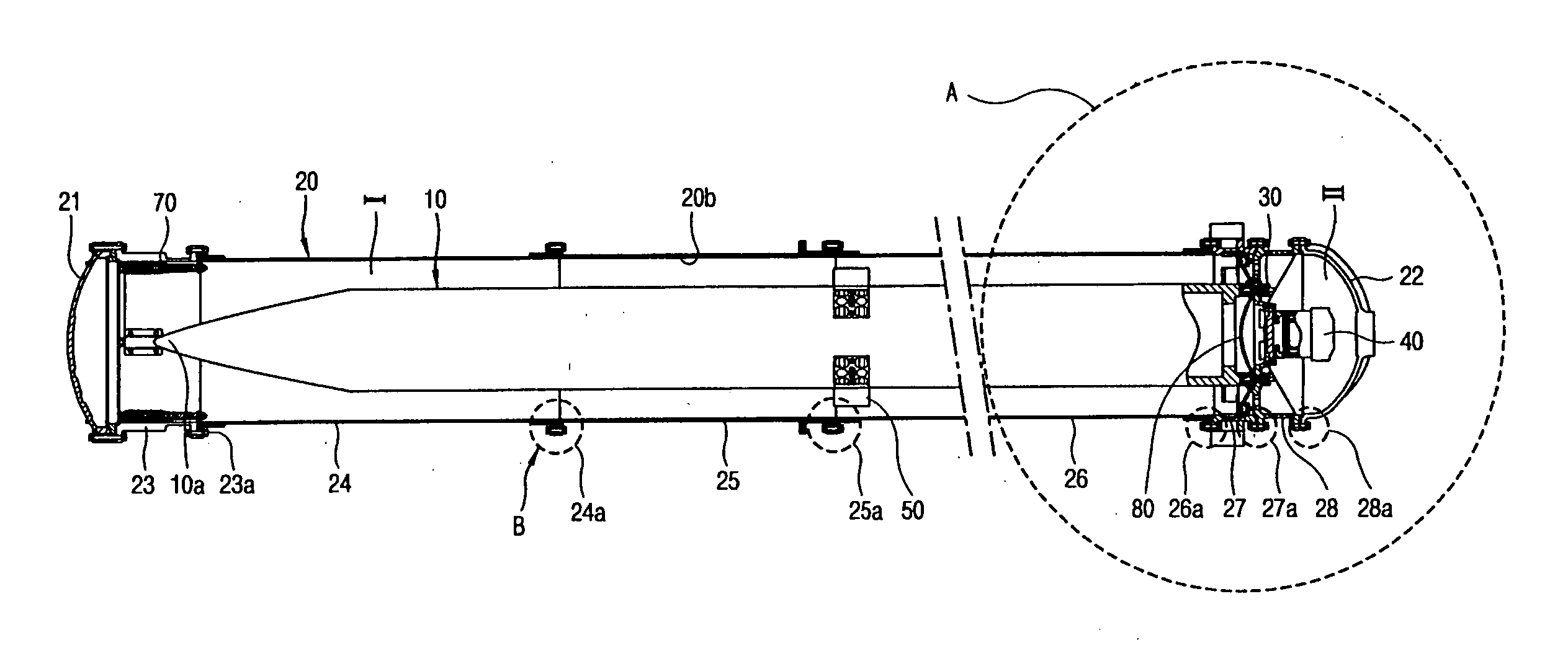
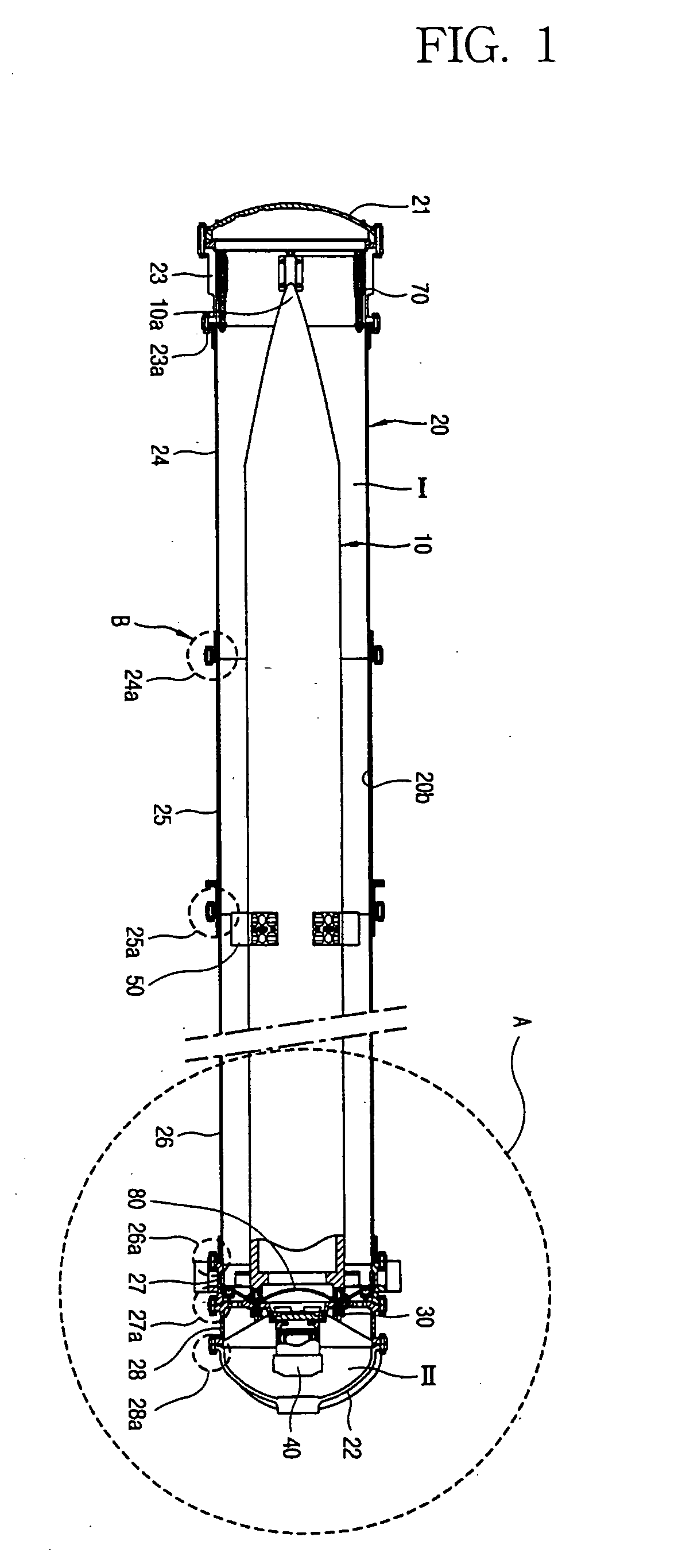
[0005] Therefore, an object of the present invention is to provide a missile ejection system which is capable of fundamentally preventing ground equipment or peripheral missiles from being damaged by releasing a missile from a canister without using a propulsion engine of the missile, thereby protecting those equipments from flames without need for a flame treatment device or a measure for protection.

Problems solved by technology

However, in this type of launching system, there is a risk that ground equipment or peripheral missiles in a launcher might be damaged due to the high temperature and high pressure flames from the missile propulsion engine.
Besides, this type of launching system had problems that a thrust loss occurs as a detent is unlocked and a missile is released by using its propulsion engine during the initial launch period.

Method used


Image

  • Missile ejection system and launching canister thereof
  • Missile ejection system and launching canister thereof
  • Missile ejection system and launching canister thereof

Examples


Embodiment Construction

[0037] Hereinafter, the present invention will be described in detail with reference to the accompanying drawings.

[0038] Detailed description of well-known functions and structures is omitted in order to clarify the key points of the present invention.

[0039] A missile ejection system 1 in accordance with one embodiment of the present invention includes a canister 20 protecting a missile 10 from the exterior disturbance before the launching of the missile 10 and serving as a cylinder during launching of the missile 10, a plurality of detents 30 restraining the missile 10 in the longitudinal direction before the launching of the missile 10, a gas generator 40 generating pressure in order to eject the missile 10 from the canister 20 in the event the missile 10 is launched, a plurality of sabots 50 fitting to the missile 10 in the canister 20 and protruding on the outer peripheral surface of the missile 10, an umbilical cable separator 60 arranged to smoothly separate a nib connector ...


PUM


Abstract

The present invention discloses a missile ejection system and a canister thereof. The missile ejection system comprises: comprising: a canister formed as a cylindrical shell, a partition wall protruding from an inner wall of the canister so as to divide the canister into a first chamber for housing a missile therewithin and a second chamber, and having at least one hole therethrough for allowing the flowing of gas through the partition wall, a gas generator secured to the partition wall in the second chamber so that a gas outlet thereof faces in an opposite direction from the first chamber, and an obturator including a sealing plate formed with a concave surface toward a fore-end of the missile for enclosing a tail end of the missile, and a radially extending skirt plate extended from the circumference of the sealing plate to the inner wall of the canister and inclined toward the fore-end of the missile for covering the space between the missile and the inner canister, wherein the missile is propelled by the pressure of the gas discharged out of the gas generator from the second chamber to the first chamber through the hole, being pressurized by the flown-in gas in the first chamber, pushing upon the obturator. Thereby, the system is able to effectively release a missile from a canister by a gas generator without using a missile propulsion engine, thereby fundamentally preventing the damage of ground equipments or peripheral missiles.

Description

BACKGROUND OF THE INVENTION [0001] 1. Field of the Invention [0002] The present invention relates to a missile ejection system and a canister thereof, and more particularly relates to a missile ejection system which is capable of fundamentally preventing ground equipment or peripheral missiles from being damaged, by releasing a missile from a canister without using a missile propulsion engine therein. [0003] 2. Description of the Background Art [0004] Up to the present, in many countries the majority of missile launching systems have been developed to be of such a type that a missile is released from a canister using a thrust generated by a propulsion ignition engine of the missile. However, in this type of launching system, there is a risk that ground equipment or peripheral missiles in a launcher might be damaged due to the high temperature and high pressure flames from the missile propulsion engine. Accordingly, a flame treatment device or a protective measure is required necessa...

Claims


Application Information

Patent Timeline
IPC IPC(8): B64C1/22B64D1/08B64D9/00
CPCF41F3/00F41F3/0413F41F3/042F41F3/073F42B5/045F42B14/064F41F3/052F42B15/00
Inventor SHIM, WOO-JEONKIM, IL-SOOOH, SEUNG-JONGHA, JAE-HOONKIM, JI-CHUL
Owner AGENCY FOR DEFENSE DEV
Learn More