
Device and applications for passive RF components in leadframes

a passive rf and leadframe technology, applied in the direction of antennas, antenna supports/mountings, radiating element structural forms, etc., can solve the problems of ancillary rf circuit passive devices required to complete a module or system, affecting the overall cost of the customer solution, and affecting the design or redesign of complex components. the realm of the end manufacturer

Inactive Publication Date: 2006-09-28
SIGE SEMICON
View PDF37 Cites 12 Cited by
  • Summary
  • Abstract
  • Description
  • Claims
  • Application Information

AI Technical Summary

Benefits of technology

[0032] According to another embodiment of the fifth aspect of the invention, wherein at least one transmission line of the two or more transmission lines is adapted to be tuned to a particular frequency or frequency range as a function of a location of attachment of the coupling means to the at least one transmissi

Problems solved by technology

In many applications the cost of filters, antennas, and other passive RF devices contribute a significant portion of a total overall cost of a customer solution.
In other words, while one might be able to provide low cost integrated circuit components such as transmitters and receivers, the ancillary RF circuit passive devices required to complete a module or system can dominate the total overall cost.
The disadvantage of this solution is that physical space required for certain types of passive RF components at particular frequencies pushes complicated design or redesign into the realm of the end manufacturer.
This may result in additional time and money being spent by the end manufacturer in developing necessary components for proper operation of the integrated circuit from the vendor.

Method used


Image

  • Device and applications for passive RF components in leadframes
  • Device and applications for passive RF components in leadframes
  • Device and applications for passive RF components in leadframes

Examples


Embodiment Construction

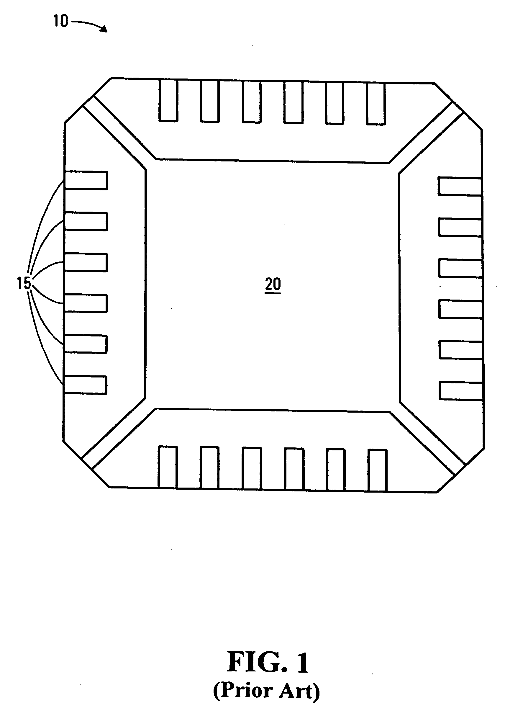
[0049]FIG. 1 illustrates a top view schematic of a conventional leadframe. The leadframe 10 has leads 15 positioned about the periphery of the leadframe 10. The leadframe also has a die flag 20, occupying a portion of the center area of the leadframe. The die flag 20 is an area upon which a semiconductor die (not shown) is mounted on the leadframe 10.

[0050] The semiconductor die can be mounted on the die flag 20 of the leadframe 10 in any number of ways known to those skilled in the art, for example attaching by epoxy, soldering or spot welding. The semiconductor die includes contact pads for providing an electrical connection to or from the semiconductor die. Electrical connectivity between the semiconductor die contact pads and the leadframe 10 can be implemented using traditional and well-known wirebonding techniques.

[0051] The leads 15 and the die flag 20 of the leadframe 10 are typically formed of a similar material and have a uniform thickness throughout the leadframe 10. On...


PUM


Abstract

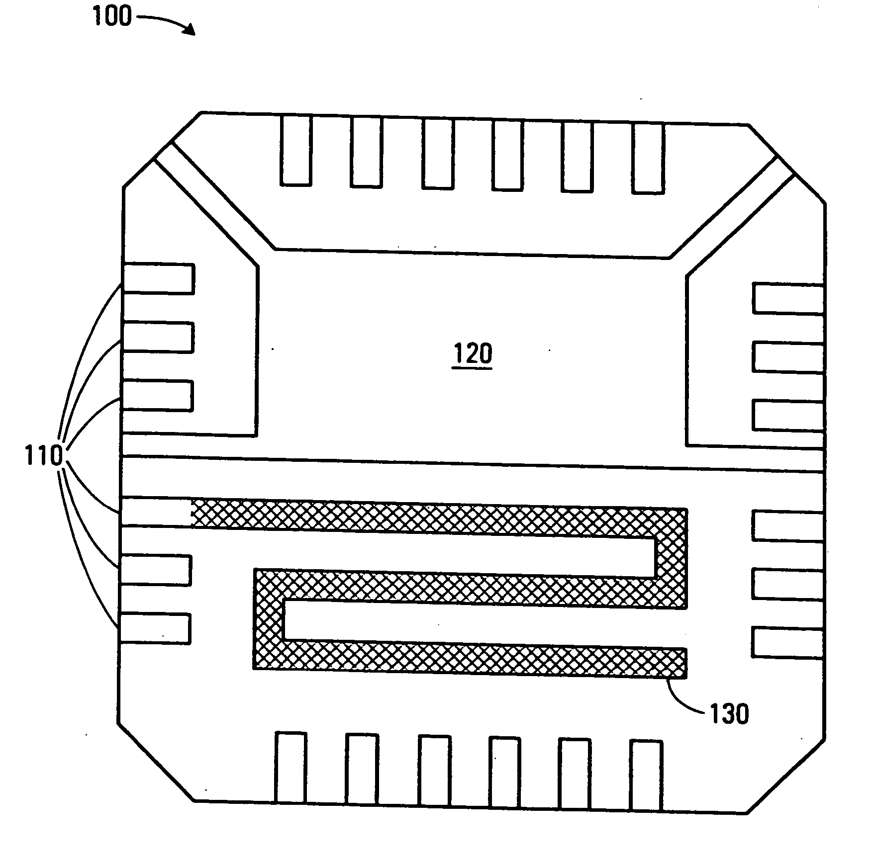
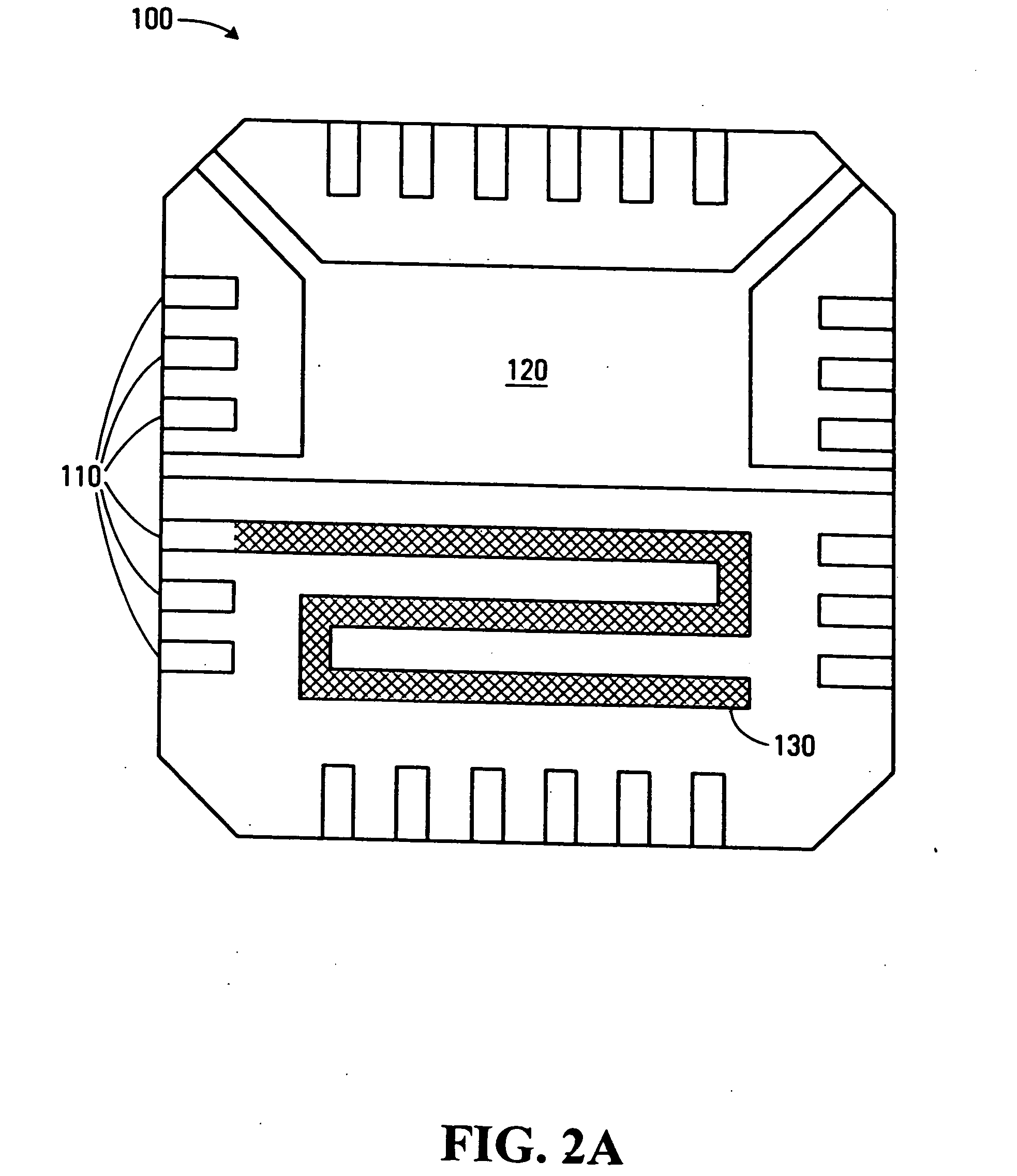
A leadframe and a semiconductor package including such a lead frame, are provided by embodiments of the invention. The leadframe includes a die flag, leads, and a radio frequency (RF) passive component integrally formed into the leadframe. Examples of the RF passive component can be an antenna, such as a spiral or serpentine antenna or one or more transmission lines that can be used as a coupler or filter. The RF passive component can also be tuned to particular frequency values and ranges depending on the particular location of attachment to the RF passive component. The semiconductor package further comprises a semiconductor die and a coupling means with which to connect to the RF passive component to another location on the leadframe, such as the leads and / or the semiconductor die. The semiconductor package may also be encapsulated in a non-conductive material to protect the semiconductor die, coupling means and RF passive component.

Description

FIELD OF THE INVENTION [0001] The invention relates to integrating passive Radio Frequency (RF) components onto a semiconductor leadframe and applications for which the leadframe can be used. BACKGROUND OF THE INVENTION [0002] In the area of wireless communication technology one aspect of research and development emphasis is directed to smaller and less expensive hardware. One of the ways to achieve smaller and less expensive hardware is integration of components so as to reduce a footprint size of the hardware involved, such as printed circuit boards (PCBs) and the components that are located on the PCBs. [0003] Many RF circuits used in wireless communication require filters and other passive device elements such as antennas. In many applications the cost of filters, antennas, and other passive RF devices contribute a significant portion of a total overall cost of a customer solution. In other words, while one might be able to provide low cost integrated circuit components such as ...

Claims


Application Information

Patent Timeline
IPC IPC(8): H01L23/495
CPCH01L23/49541H01L23/66H01L2224/48091H01L2924/3011H01Q1/22H01Q1/2283H01Q1/38H01Q9/30H01L2924/00014H01L24/48H01L2924/14H01L2924/00H01L2224/45099H01L2224/45015H01L2924/207
Inventor LORAINE, JEREMYKOVACIC, STEPHEN J.
Owner SIGE SEMICON
Learn More