Antenna apparatus

Inactive Publication Date: 2006-09-28
TOYOTA JIDOSHA KK
View PDF13 Cites 3 Cited by
  • Summary
  • Abstract
  • Description
  • Claims
  • Application Information

AI Technical Summary

Benefits of technology

[0010] In the door-mirror-mounted antenna apparatus according to the present invention, the pitch of the coil-shaped portion of the antenna is fixed by the securing portion provided inside the antenna case. Therefore, vibration of the coil-shaped portion of the antenna inside the antenna case (which can be a source of noise) is suppressed, and deformation of the coil-shaped portion (which changes the impedance of the antenna) is suppressed. Accordingly, the performance of the antenna can be maintained at a high level.
[0011] In carrying out the present invention, a base end portion of the antenna may be connected to a predetermined portion of a substrate mounted in the antenna case, and a ground connecting portion of the substra

Problems solved by technology

As a result, there is the possibility of the impedance of the antenna (whic

Method used


Image

  • Antenna apparatus
  • Antenna apparatus
  • Antenna apparatus

Examples


Example

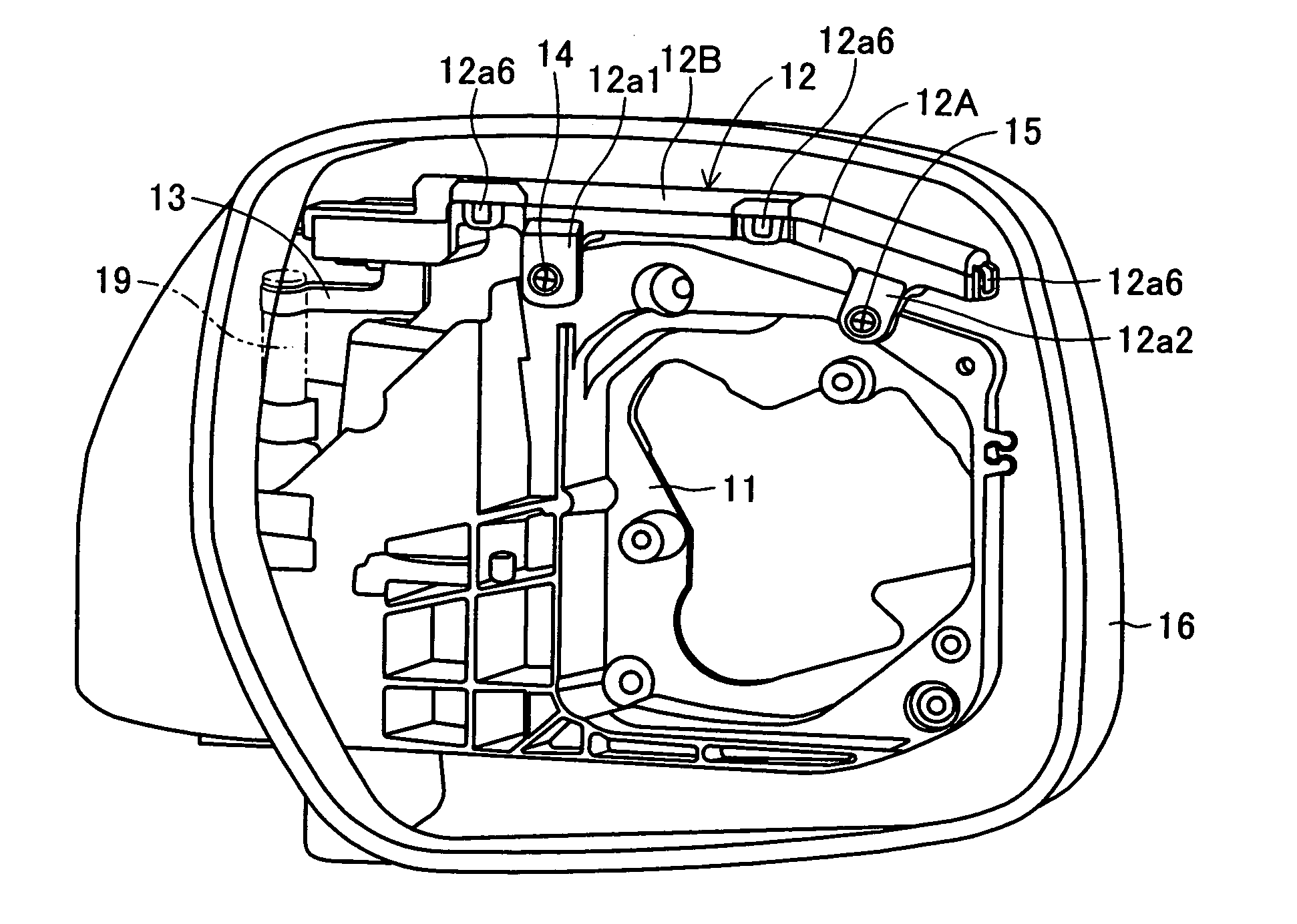
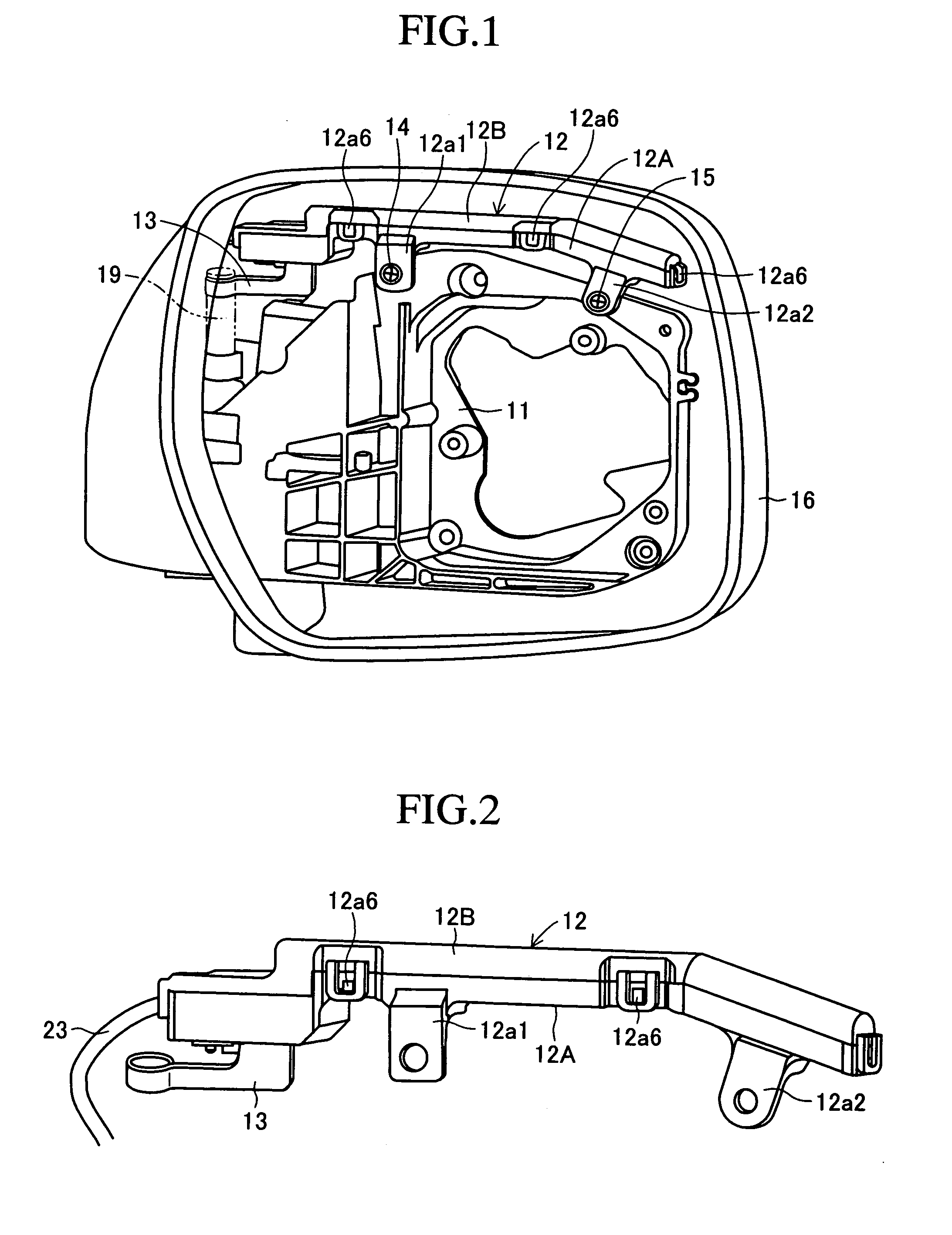
[0022] Below, an embodiment of the present invention will be described while referring to the accompanying drawings. FIGS. 1 to 8 illustrate an embodiment of an antenna apparatus according to the present invention housed inside a door mirror of a vehicle, i.e., they illustrate a door-mirror-mounted antenna apparatus. In this embodiment, an antenna case 12 is mounted on a mirror bracket 11 by a pair of screws 14 and 15. The mirror bracket 11 is formed in a prescribed shape from metal, and it is housed inside a door mirror housing 16. In this embodiment, a grounding plate 13 is rotatably connected to a metal shaft 19. The shaft 19 is mounted on and electrically grounded by the body (not shown) of the vehicle. The shaft 19 rotatably supports the mirror bracket 11.

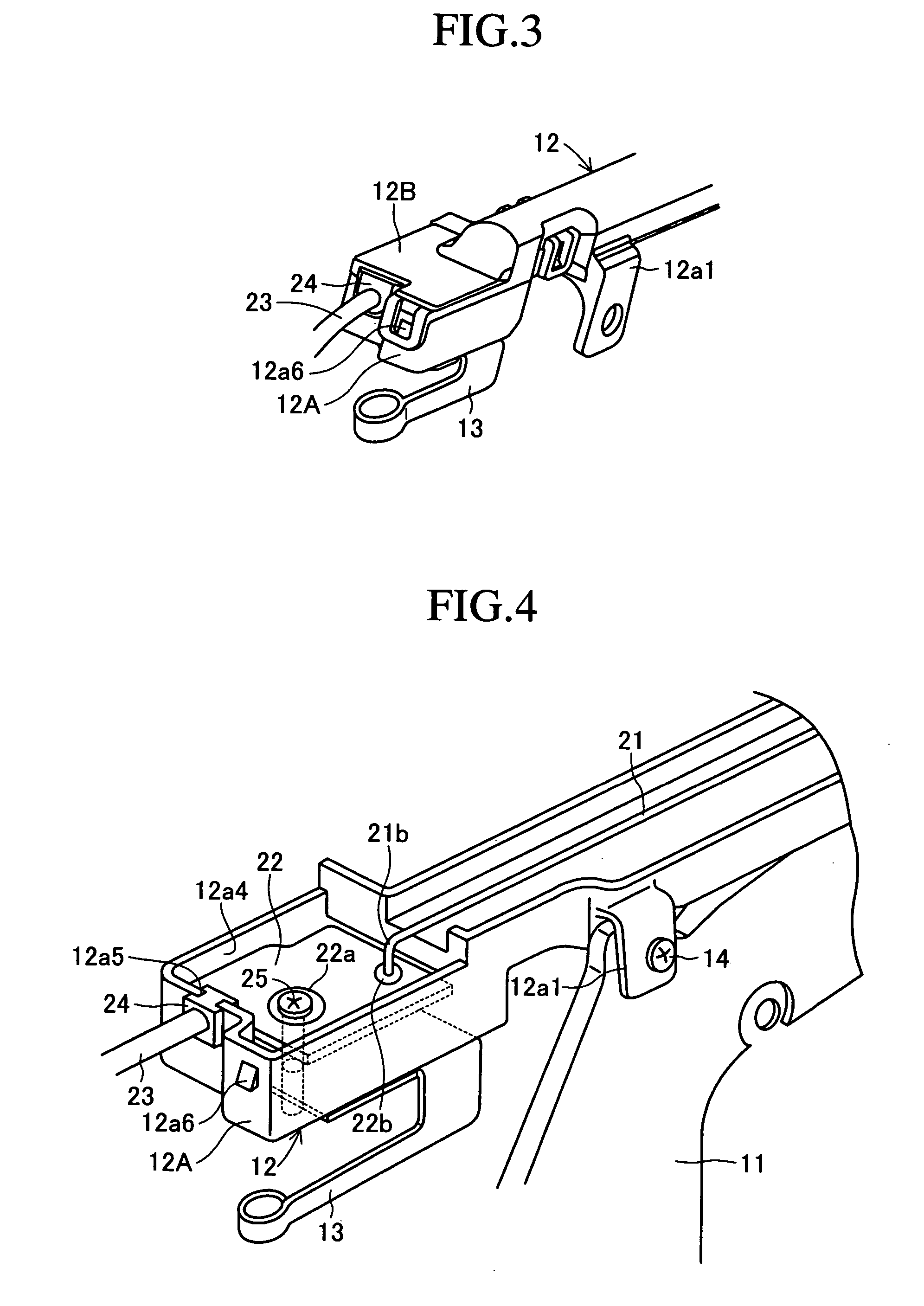
[0023] The antenna case 12 comprises a lower portion 12A which is mounted on the mirror bracket 11 and an upper portion 12B which is detachably mounted on the lower portion 12A. Both portions 12A and 12B are made of a difficu...


PUM


Abstract

An antenna apparatus includes an antenna case and an antenna disposed inside the antenna case. The antenna includes a coil-shaped portion which engages with a securing portion of the antenna case so as to fix the pitch of the coil-shaped portion. The antenna case may be formed of a difficult to deform electrically insulating material. A base end portion of the antenna is connected to a predetermined portion of a substrate mounted inside the antenna case, and a ground connecting portion of the substrate is electrically connected to a rust resistant connecting member which is provided outside the antenna case and is grounded. In a preferred embodiment, the antenna is mounted in a door mirror of a vehicle.

Description

BACKGROUND OF THE INVENTION [0001] 1. Field of the Invention [0002] The present invention relates to an antenna apparatus having an antenna housed inside an antenna case (also referred to as an antenna cover), with a portion of the antenna having the shape of a coil. [0003] 2. Description of the Related Art [0004] An example of an antenna apparatus of the type to which the present invention relates is disclosed in Japanese Patent Application Laid-Open (kokal) No. H9-102707. In that document, a coil-shaped portion of an antenna is covered by a flexible heat shrink tube, and the coil-shaped portion which is covered by the heat shrink tube is housed inside an elastic antenna cover. [0005] In the antenna apparatus described in that document, the heat shrink tube is flexible, so there is the possibility of the coil-shaped portion of the antenna vibrating and deforming inside the antenna cover. As a result, there is the possibility of the impedance of the antenna (which greatly affects th...

Claims


Application Information

Patent Timeline
IPC IPC(8): H01Q1/32
CPCH01Q1/3266H01Q7/08H01Q11/08
Inventor IDE, NOBUHIRO
Owner TOYOTA JIDOSHA KK
Why Eureka
Try Eureka