Display apparatus
a technology of display apparatus and display screen, which is applied in the direction of static indicating device, cathode-ray tube indicator, instruments, etc., can solve the problems of easy deterioration of unit pixels having large luminance in fixed pictures, deterioration of light use efficiency, etc., and achieves suppression of burn-in and reducing dispersion of pixel deterioration
- Summary
- Abstract
- Description
- Claims
- Application Information
AI Technical Summary
Benefits of technology
Problems solved by technology
Method used
Image
Examples
first embodiment
[0123] [1] RGB-RGBW Signal Converter
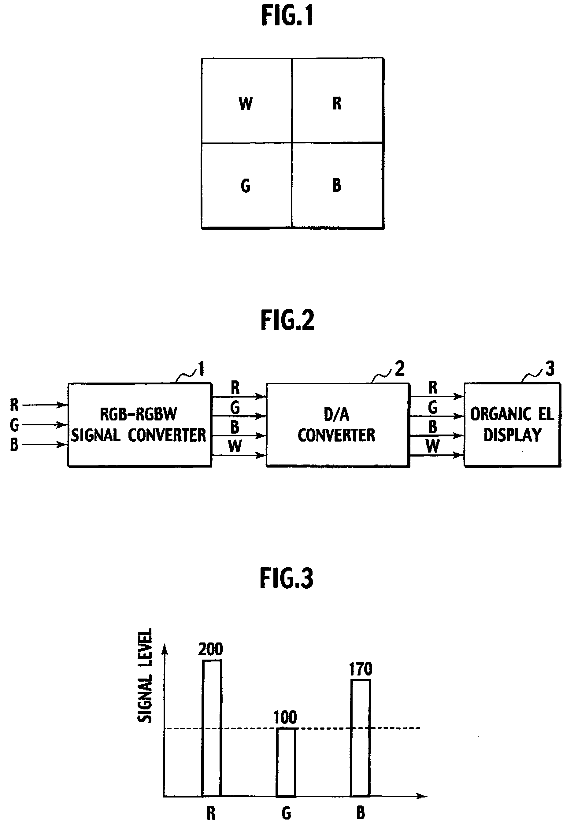
[0124] First, an RGB-RGBW signal converter used in a first embodiment of the present invention will be described. The RGB-RGBW signal converter used in the first embodiment uses a processing that is almost the same as the third RGB-RGBW conversion processing described with reference to FIG. 23 to convert an RGB signal to an RGBW signal. However, this processing is different from the third RGB-RGBW conversion processing in that a W usage rate (RGB-RGBW conversion ratio) can be controlled.
[0125]FIG. 24 shows a procedure of the RGB-RGBW signal conversion processing by the RGB-RGBW signal converter used in the first embodiment.
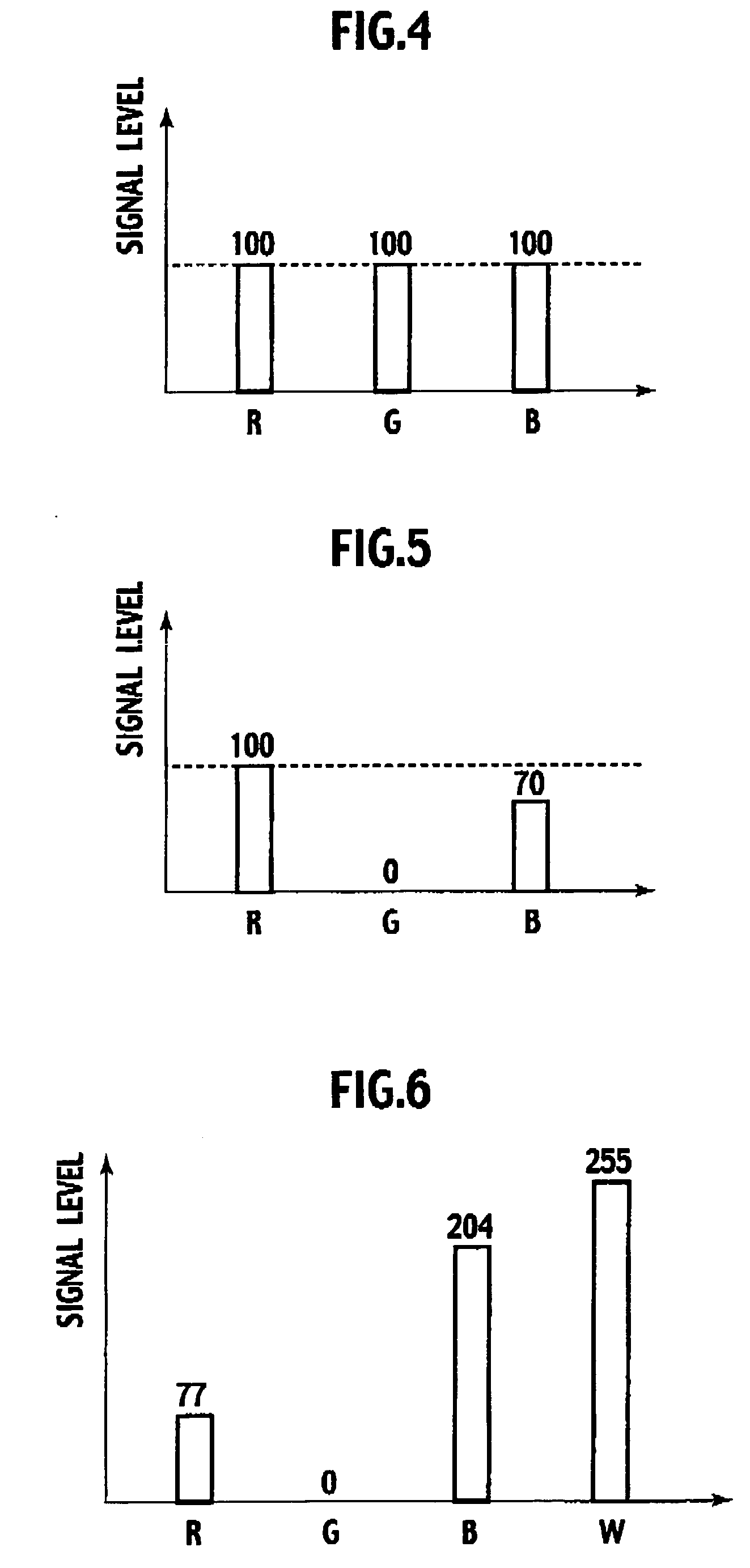
[0126] First, an RGB signal feedback ratio is calculated by an RGBW signal value for representing a target white Wt (255) when R, G, and B input signal values are all 255 (step S51). When assuming that the RGBW signal value for representing the target white Wt (255) has a signal value as shown in FIG. 6, then the RGB signal f...
second embodiment
[0145] [1] RGB-RGBW Signal Converter
[0146] The conversion processing method by the RGB-RGBW signal converter used in a second embodiment is the same as the conversion processing method by the RGB-RGBW signal converter of the first embodiment shown in FIG. 24.
[0147] [2] Outline of Second Embodiment
[0148] A display apparatus including an RGBW type organic EL display may display an image including an icon. In the display area of the icon (icon display region), a unit pixel among RGB, and W unit pixels that has a large amount of emission tends to deteriorate. When a W usage rate a is 100% as in a conventional case, a W unit pixel in the display area of the icon tends to deteriorate.
[0149] In view of the above, the second embodiment uses, when an icon is displayed, a W usage rate α of 100[%] in a display area other than the icon display region (no-icon display region) and uses a W usage rate a lower than 100[%] in the icon display region. As a result, the icon display region has equa...
third embodiment
[0161] [1] RGB-RGBW Signal Converter
[0162] The conversion processing method by the RGB-RGBW signal converter used in a third embodiment of the present invention is the same as the conversion processing method by the RGB-RGBW signal converter of the first embodiment shown in FIG. 24
[0163] [2] Outline of Third Embodiment
[0164] In the third embodiment, for each pixel, the total light emission amount to the present stage of the respective RGB, and W unit pixels constituting the pixel (accumulation value of signal levels in the respective frames to the present stage) is calculated. Then, when a difference ΔS between the maximum value of the total light emission amount to the present stage of the respective RGB, and W unit pixels and the total light emission amount to the present of the W unit pixel is larger than a threshold value H, then the W usage rate a to this pixel is set to have a value equal to or lower than 100[%]. When ΔS is lower than a threshold value L, then the value of t...
PUM
 Abstract
Description
Claims
Application Information
 - R&D
- Intellectual Property
- Life Sciences
- Materials
- Tech Scout
- Unparalleled Data Quality
- Higher Quality Content
- 60% Fewer Hallucinations
Browse by: Latest US Patents, China's latest patents, Technical Efficacy Thesaurus, Application Domain, Technology Topic, Popular Technical Reports.
© 2025 PatSnap. All rights reserved.Legal|Privacy policy|Modern Slavery Act Transparency Statement|Sitemap|About US| Contact US: help@patsnap.com


