Method and system for camera autocalibration

a technology of automatic calibration and camera, applied in the field of visual surveillance, can solve the problems of difficult to obtain and rare availability of calibration information

Inactive Publication Date: 2006-09-28
UTC FIRE & SECURITY AMERICAS CORPORATION INC
View PDF6 Cites 37 Cited by
  • Summary
  • Abstract
  • Description
  • Claims
  • Application Information

AI Technical Summary

Benefits of technology

[0005] Conventional surveillance systems have dealt with small amounts of measurement noise and outl...

Problems solved by technology

Unfortunately, calibration information is rarely available and...

Method used


Image

  • Method and system for camera autocalibration
  • Method and system for camera autocalibration
  • Method and system for camera autocalibration

Examples


Embodiment Construction

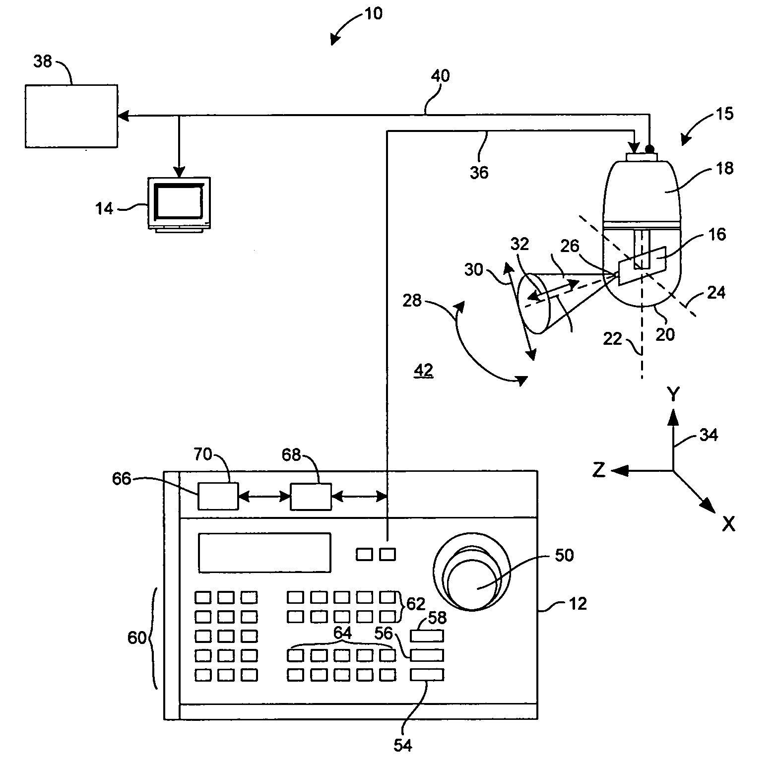
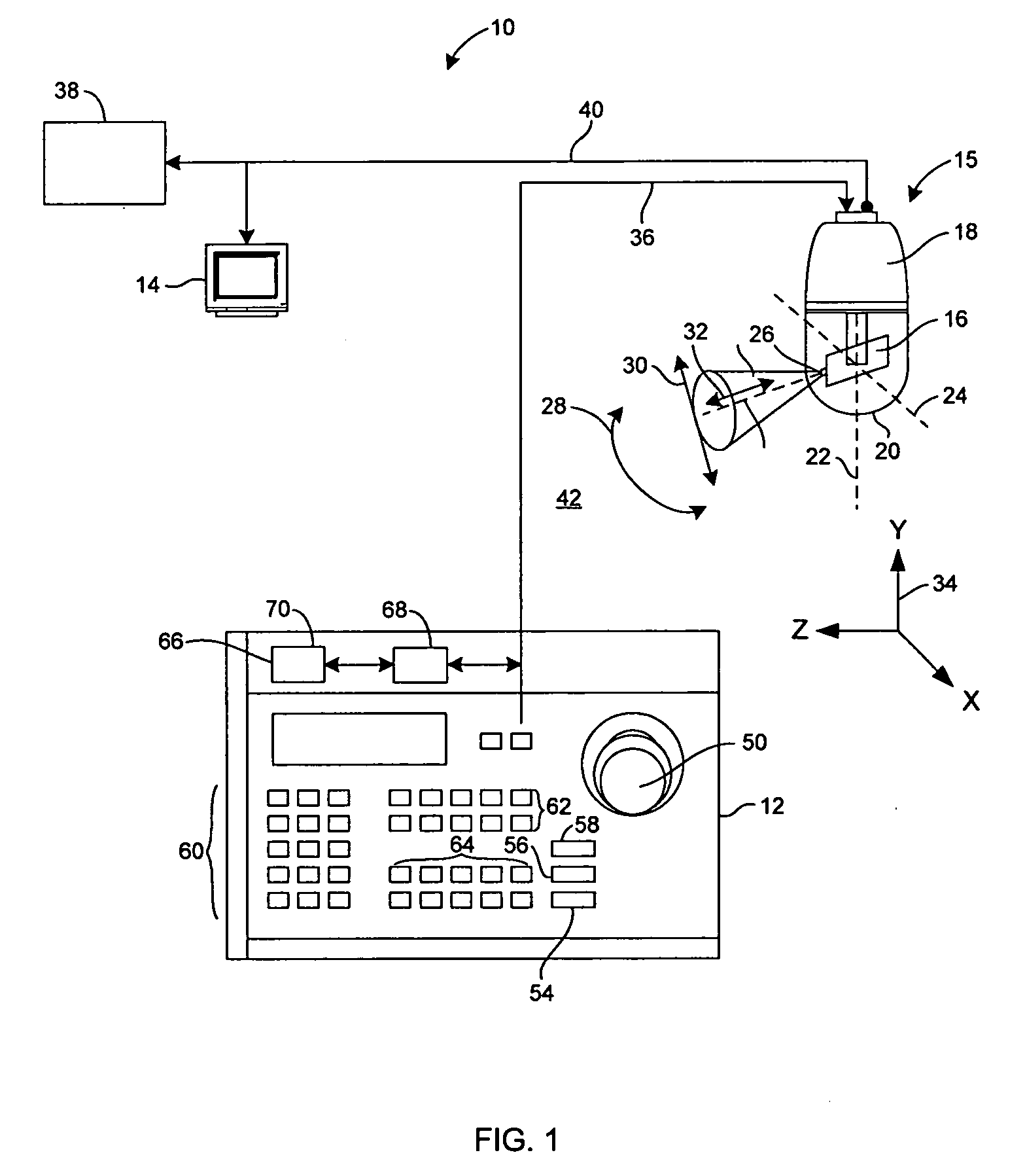
[0013] The present invention provides a method and system for automatically calibrating a projective camera for a surveillance system based on information gathered by detecting objects, such as at least one person, along a ground plane. Calibration parameter measurements are obtained by utilizing a foot-to-head plane homology. Initial parameters can then be efficiently estimated from these calibration parameter measurements. A Bayesian solution, which is capable of handling measurement uncertainties, outliers and prior information, is utilized to solve conventional calibration problems dealing with noise analysis. Further, given the calibration parameter measurements, a full posterior distribution of calibration parameters can be accurately estimated.

[0014]FIG. 1 is a schematic view of an exemplary video surveillance system 10 in accordance with one embodiment. Video surveillance system 10 includes a control panel 12, a display monitor 14, and a video camera assembly 15. In one emb...


PUM


Abstract

A method for calibrating a projective camera is provided. The method includes acquiring information by detecting at least one object on a substantially flat ground plane within a field of view. A projective camera calibration is performed. A measurement uncertainty is considered to yield a plurality of camera parameters from the projective camera calibration.

Description

CROSS REFERENCE TO RELATED APPLICATIONS [0001] This application claims the benefit of U.S. Provisional Application No. 60 / 661,540, filed Mar. 14, 2005, which is hereby incorporated by reference in its entirety.BACKGROUND OF THE INVENTION [0002] This invention relates generally to visual surveillance and, more particularly, to a method and system for projective camera calibration. [0003] In the context of visual surveillance of human activity, for example, knowledge about a camera's internal and external parameters is useful, as it allows for the establishment of a connection between image and world measurements. Unfortunately, calibration information is rarely available and difficult to obtain after a surveillance system has been installed. [0004] The connection between image measurements and scene measurements in metric space is greatly simplified when intrinsic and extrinsic parameters of the camera are available. The two general approaches to establish these parameters are known ...

Claims


Application Information

Patent Timeline
IPC IPC(8): H04N7/18H04N17/00
CPCG06T7/0018G06T7/80
Inventor KRAHNSTOEVER, NILS OLIVERMENDONCA, PAULO RICARDORITTSCHER, JENSSEBASTIAN, THOMAS BABYTU, PETER HENRY
Owner UTC FIRE & SECURITY AMERICAS CORPORATION INC
Why Eureka
Try Eureka