
Method and apparatus for measuring polarization

a technology of polarization and measurement method, applied in the direction of optical radiation measurement, measurement device, instruments, etc., can solve the problem that instantaneous temporal information lost through averaging cannot be retrieved later

Inactive Publication Date: 2006-09-28
LUCENT TECH INC
View PDF5 Cites 2 Cited by
  • Summary
  • Abstract
  • Description
  • Claims
  • Application Information

AI Technical Summary

Benefits of technology

"The patent describes an improved method and apparatus for measuring the polarization of light using nonlinear polarimetry. The method involves measuring the higher order moments of the E field and transforming them into standard polarimetry parameters to determine the polarization of the light. The apparatus includes a rotating retarder and a fixed analyzer, or a plurality of fiber birefringences and polarization sensitive gratings. The technical effects of the invention include improved accuracy and precision in measuring polarization, as well as simplified and more efficient apparatus design."

Problems solved by technology

The problem with averaging at detection is that instantaneous temporal information lost through averaging cannot be retrieved later.

Method used


Image

  • Method and apparatus for measuring polarization
  • Method and apparatus for measuring polarization
  • Method and apparatus for measuring polarization

Examples


examples

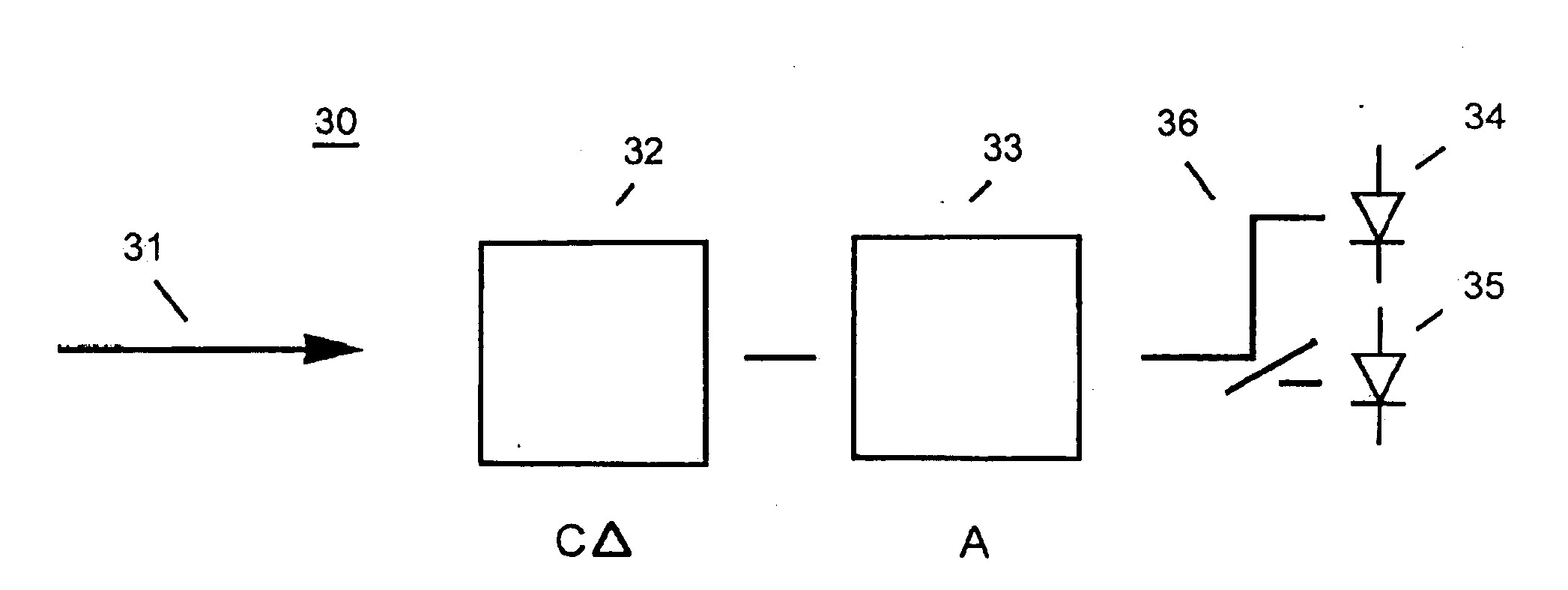
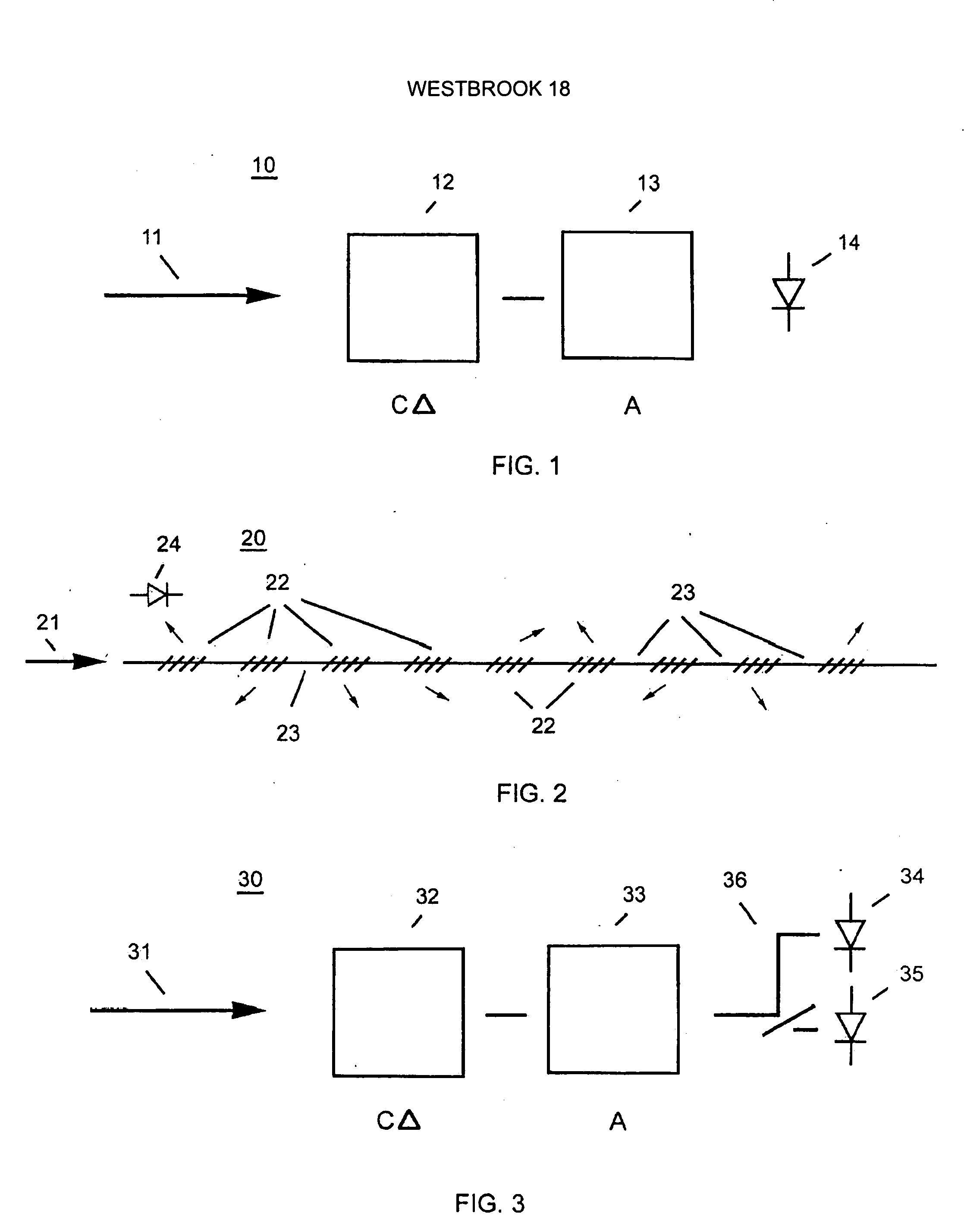
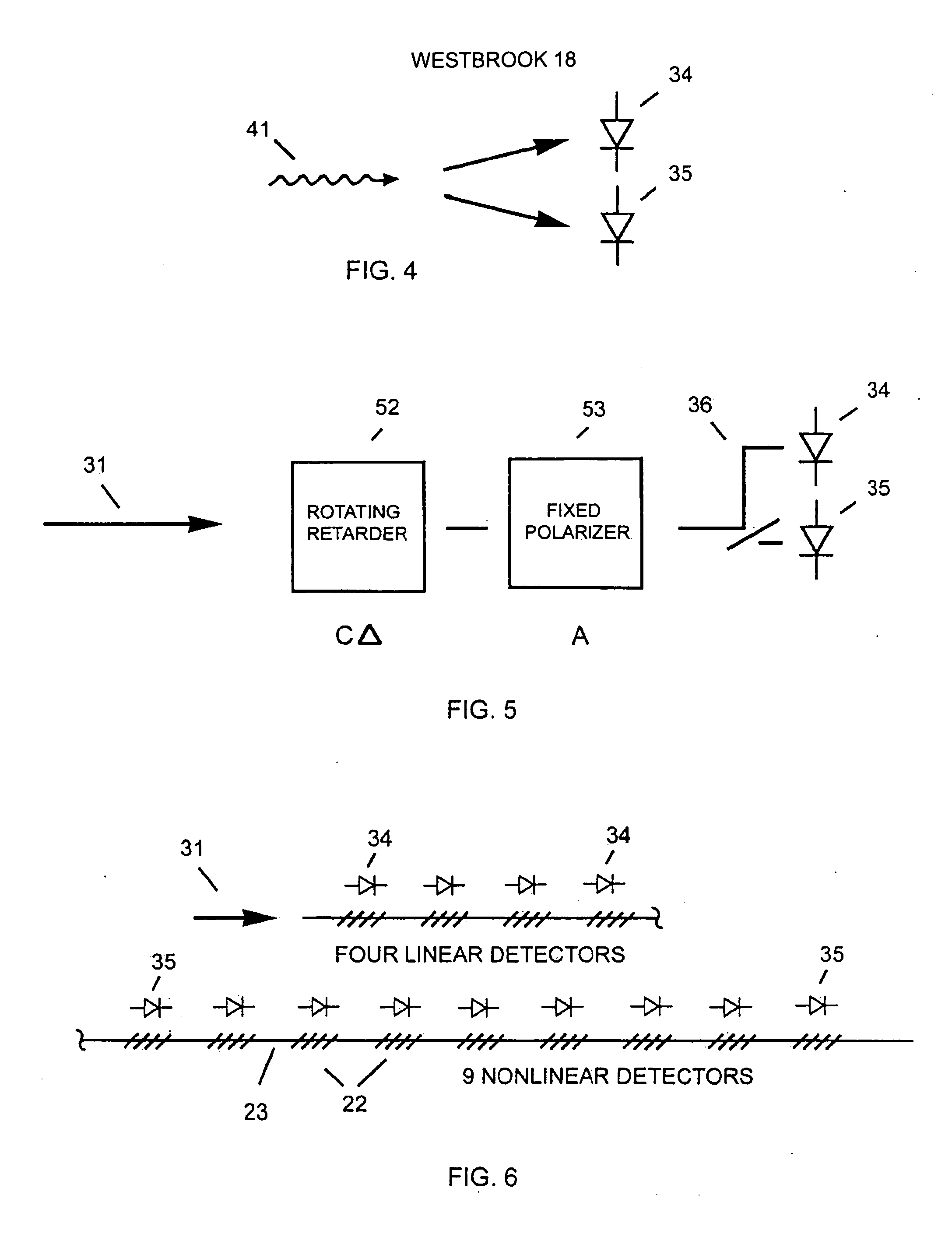
[0038]FIG. 5 shows a first preferred embodiment of the nonlinear polarimeter. Here, rotating retarder 52 receives light 31. Fixed polarizer 53 is optically coupled to rotating retarder 52 and coupler 36. Coupler 36 splits the light from fixed polarizer 53 to the two photodetectors, linear detector 34 and nonlinear detector 35. This embodiment can be accomplished in bulk optics or by using integrated electro-optics fabrication techniques.

[0039]FIG. 6 shows a second preferred embodiment of a nonlinear polarimeter to accomplish static measurement of the moments. Here, fiber 23 receives light 31. The light from polarization sensitive gratings 22 is detected by four linear detectors 34 and nine nonlinear detectors 35. Each polarization sensitive gratings 22 has a different scattering angle. Birefringent optical fiber 23 causes the birefringences. In the limit of weak scattering for each grating, the scattered E-field is the same as in the case of specific retarder and the analyzer posit...


PUM


Abstract

A method of nonlinear polarimetry for measuring higher order moments of the E field of an optical signal is provided. The method includes imposing a phase delay on a first polarization of a received optical signal with respect to a second polarization of the optical signal to produce an intermediate optical signal having a time varying polarization. A polarization of the intermediate optical signal is suppressed. The intermediate optical signal is detected with a plurality of photodetectors, with at least one photodetector configured to be responsive to a nonlinear optical process. Spectra of the photodetector outputs are calculated to determine higher order moments of the E field, and the moments are transformed to obtain the polarization measurement.

Description

CROSS-REFERENCE TO RELATED APPLICATION [0001] This Application is a Divisional of prior application Ser. No. 10 / 413,962 filed on Apr. 15, 2003, currently pending, to Paul S. Westbrook. The above-listed Application is commonly assigned with the present invention and is incorporated herein by reference as if reproduced herein in its entirety under Rule 1.53(b).TECHNICAL FIELD OF THE INVENTION [0002] This invention relates to a method and apparatus for measuring the polarization of light. BACKGROUND OF THE INVENTION [0003] High-speed optical fiber communication systems operate by encoding information (data) onto lightwaves that typically propagate along optical fiber paths. Most systems, especially those used for medium to long distance transmission employ single mode fiber. As implied by the name, single mode fibers propagate only one mode of light below cutoff. The single mode typically includes many communications channels. The communications channels are combined into the one trans...

Claims


Application Information

Patent Timeline
Patent Type & Authority Applications(United States)
IPC IPC(8): G01J4/00
CPCG01J4/00
Inventor WESTBROOK, PAUL STEPHEN
Owner LUCENT TECH INC
Learn More