System for monitoring the geometry of a radiation treatment apparatus, trackable assembly, program product, and related methods

a radiation treatment apparatus and geometry technology, applied in the field of patient therapy, can solve the problems of serious complications, radiation dose may not be delivered to the correct location in the patient's body, and use of the necessary effective radiation dos

Active Publication Date: 2006-09-28
BEST MEDICAL INT
View PDF32 Cites 36 Cited by
  • Summary
  • Abstract
  • Description
  • Claims
  • Application Information

AI Technical Summary

Benefits of technology

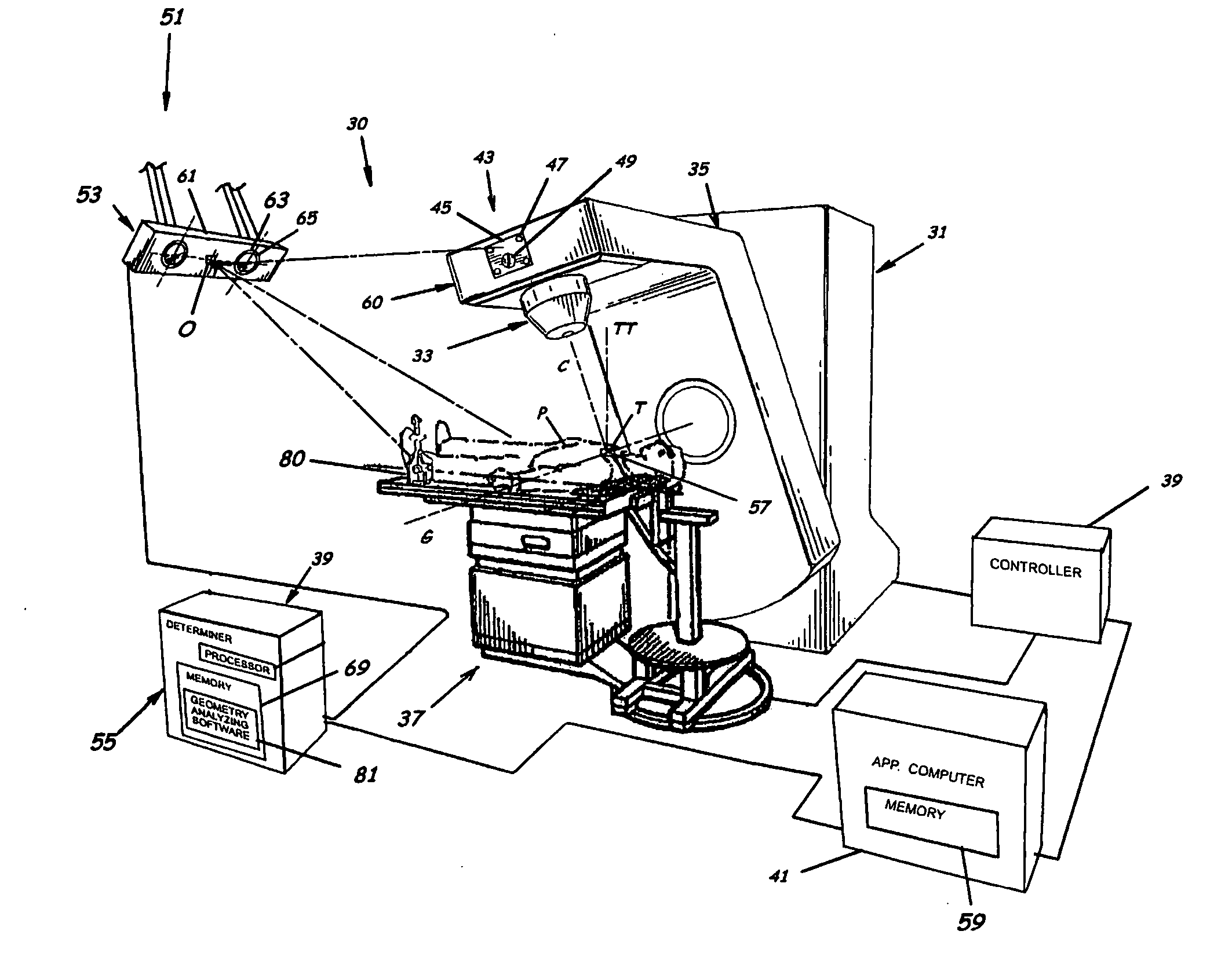
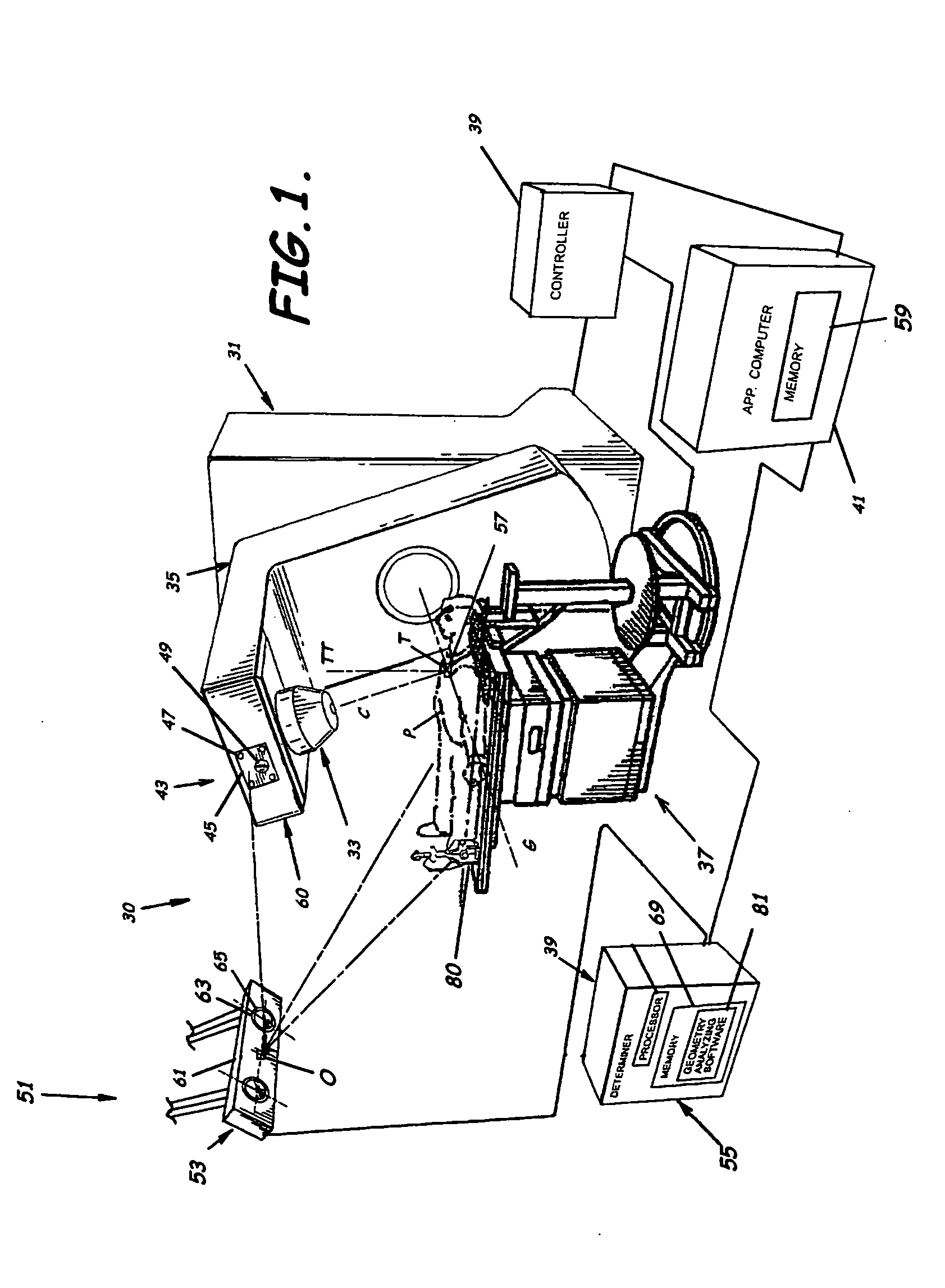
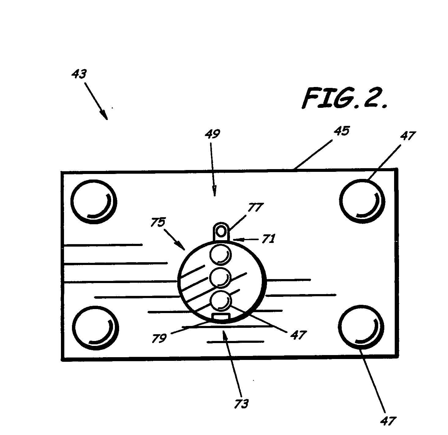
[0041] Advantageously, embodiments of the present invention may negate the requirement for a specific quality assurance check to determine if inadvertent changes have occurred in the calibrated position of a calibrated tracking system indicating the isocenter of the isocenter coordinate system. The embodiments of the present invention can utilize a trackable assembly which can be fixedly positioned in relationship to a predetermined isocenter position to continuously indicate the location and orientation of the isocenter coordinate system. Conveniently, the trackable assembly can be mounted to the radiation delivery or treatment apparatus at a very near distance in relation to the physical isocenter position, making it viewable substantially throughout the treatment delivery. Advantageously, negated is the requirement for a stable or in any other way precisely calibrated camera or optical detection / tracking system or apparatus, the trackable assembly, rather than the camera or optical detection / tracking system or apparatus, can act as a fixture with respect to the physical isocenter position. Advantageously, however, in an embodiment of the present invention, when the trackable system or apparatus is precisely calibrated to the isocenter position, the system is overspecified, and provides the operator verification of the definition of the isocenter coordinate system. Advantageously, embodiments of the present invention can include multiple trackable bodies to provide for all six degrees of freedom of the various rotating assemblies and the patient target (e.g. target tumor) while indicating the location of the isocenter and orientation of the isocenter coordinate system. The continuous position and orientation availability, during radiation delivery, of the trackable assembly and / or other trackable bodies allows for continuous, instantaneous measurement and verification of the tracking system's definition of the isocenter and / or orientation of the isocenter coordinate system as well as the continuous, instantaneous verification of the position and orientation of all items being tracked.

Problems solved by technology

Complications, however, may result from use of the necessary effective radiation dose, due to damage to healthy tissue which surrounds the target, or to other healthy body organs located close to the target.
If the effective radiation dose is not delivered to the proper location within the patient, serious complications may result.
If this positional relationship is not correct, the radiation dose may not be delivered to the correct location within the patient's body, possibly under treating the target tumor or lesion and damaging healthy surrounding tissue and organs.
Recognized by the Applicants, however, is that the above described methodologies of determining isocenter generally do not account for continuing degradation of the gantry during the actual delivery of the radiation treatment.
Also, existing systems, which indicate to the operator the position of the isocenter coordinate system, i.e., the above described lasers, are not accessible during the course of the radiation treatment.
Also recognized, however, is that these systems are vulnerable to inadvertent changes in that calibrated position.

Method used


Image

  • System for monitoring the geometry of a radiation treatment apparatus, trackable assembly, program product, and related methods
  • System for monitoring the geometry of a radiation treatment apparatus, trackable assembly, program product, and related methods
  • System for monitoring the geometry of a radiation treatment apparatus, trackable assembly, program product, and related methods

Examples


Embodiment Construction

[0055] The present invention will now be described more fully hereinafter with reference to the accompanying drawings, which illustrate embodiments of the invention. This invention may, however, be embodied in many different forms and should not be construed as limited to the illustrated embodiments set forth herein. Rather, these embodiments are provided so that this disclosure will be thorough and complete, and will fully convey the scope of the invention to those skilled in the art. Like numbers refer to like elements throughout. Prime notation, if used, indicates similar elements in alternative embodiments.

[0056] Successful therapy treatments, such as, for example, radiation therapy, rely on the ability to accurately locate and define a radiation beam. The spatial position of the radiation beam is defined by the physical geometry of the treatment apparatus. The geometry of rotating assemblies of the treatment apparatus define a coordinate system of the treatment apparatus, whic...


PUM


Abstract

A system to monitor a geometry of a treatment apparatus, an apparatus, a trackable assembly, program product, and methods are provided. The system includes a treatment apparatus having a radiation emitter, a rotating assembly controlled by a controller, and an application computer, which provides treatment delivery instructions to the controller. The system can also include a trackable assembly connected to the rotating assembly and having a fixedly connected first trackable body which functions as a reference fixture and a pivotally connected second trackable body which provides data used to determine a rotation angle of the rotating assembly. The system also includes an apparatus to track a trackable body which has a trackable body detector to detect a position of the indicators carried by the first and the second trackable bodies and a determiner to determine and verify the location of the origin of an isocenter coordinate system and to determine rotational path data about the rotating assembly.

Description

1. RELATED APPLICATIONS [0001] This application is related to and claims priority to and the benefit of U.S. Provisional Application No. 60 / 664,513, filed on Mar. 23, 2005, incorporated herein by reference in its entirety.BACKGROUND OF THE INVENTION [0002] 1. Field of the Invention [0003] The present invention relates to patient therapy. More specifically, the present invention relates to a system, a trackable assembly, program product, and related methods for monitoring a geometry of a radiation treatment apparatus to verify the origin and directions of a coordinates system used during treatment plan delivery. [0004] 2. Description of the Related Art [0005] Radiation therapy can be effective in treating certain types of cancerous tumors, lesions, or other “targets.” A vast majority of such targets can be eradicated completely if a sufficient radiation dose is delivered to the tumor or lesion volume. Complications, however, may result from use of the necessary effective radiation do...

Claims


Application Information

Patent Timeline
Patent Type & Authority Applications(United States)
IPC IPC(8): A61N5/10
CPCA61N5/1049A61N2005/1059A61N5/10
Inventor SCHERCH, JOHN DAVIDSMETAK, EDWARD CHARLES
Owner BEST MEDICAL INT
Why Eureka
Try Eureka