Bone-fixation device

a technology of proximal femur and stabilization device, which is applied in the field of proximal femur biomechanics to achieve the effect of improving the biomechanics of the proximal femur and improving the stability

Active Publication Date: 2006-09-28
SYNTHES USA
View PDF99 Cites 124 Cited by
  • Summary
  • Abstract
  • Description
  • Claims
  • Application Information

AI Technical Summary

Benefits of technology

[0032] the arms can be severed better because of the lesser wall thickness.
[0033] In yet a further embodiment, the arms are connected by crosspieces transversely to the longitudinal axis of the central plate. As a result, the advantage can be achieved that the sleeves may be connected in such a manner with

Problems solved by technology

Otherwise, the biomechanics of the proximal femur might be adversely affected appreciably; the trochanter stabi

Method used


Image

  • Bone-fixation device
  • Bone-fixation device
  • Bone-fixation device

Examples


Embodiment Construction

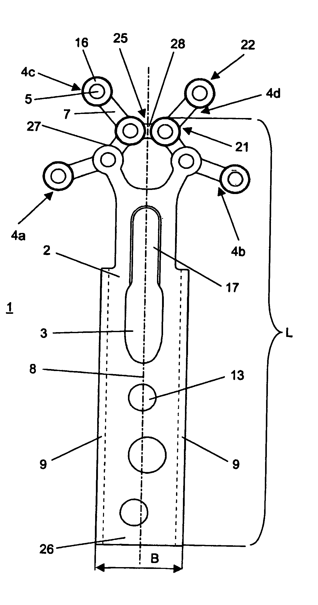
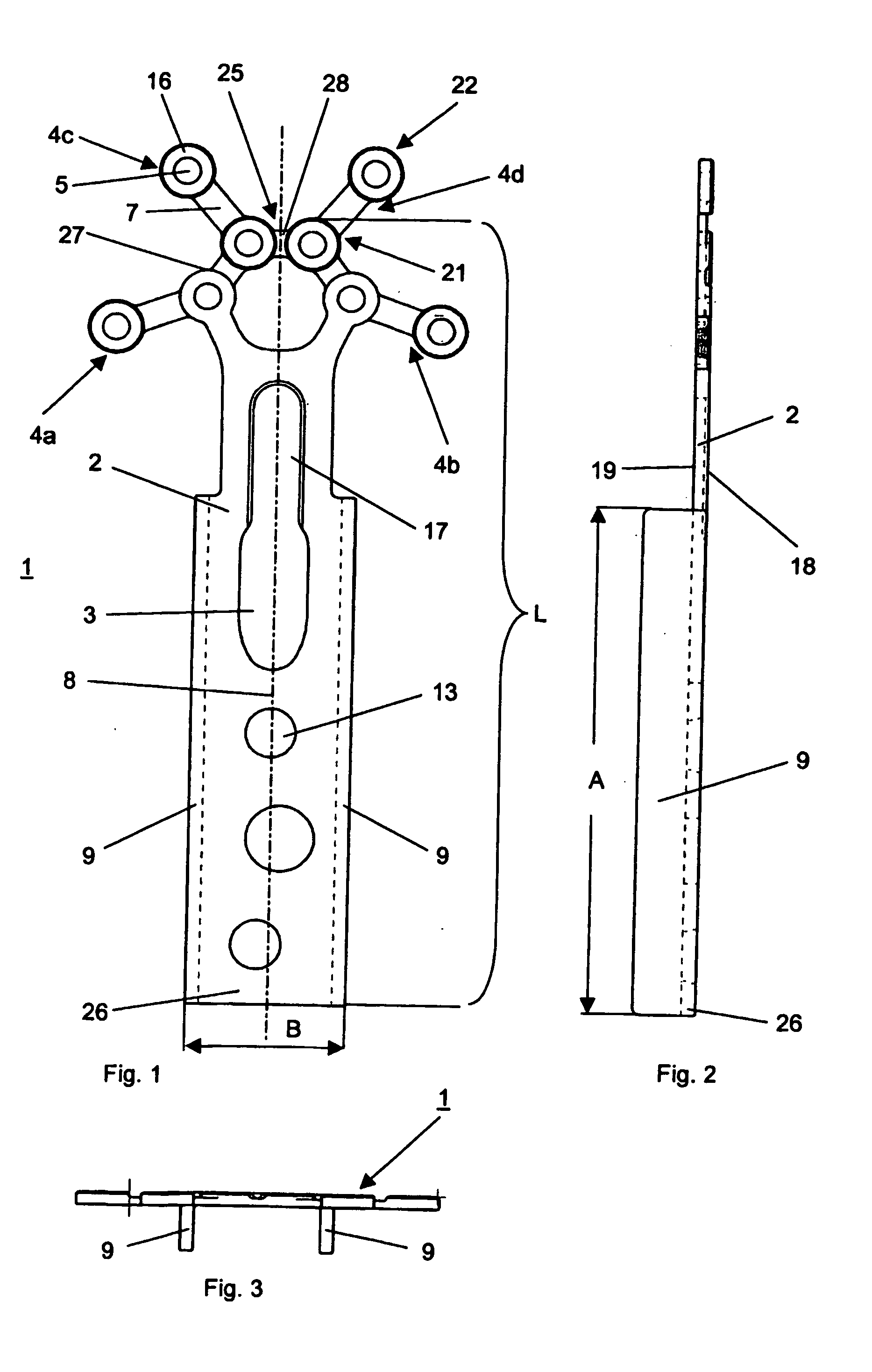
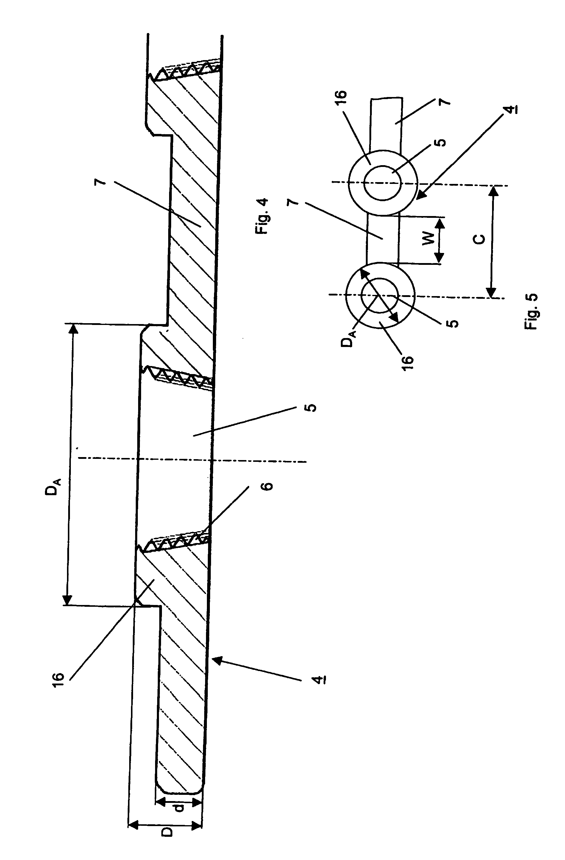
[0046] According to FIGS. 1 to 4, the bone stabilization means 1 comprises a central plate 2 with a longitudinal axis 8, an outer surface 18, which is averted from the bone 10, an inner surface 19 and four peripheral arms 4, which are angled or offset with respect to the longitudinal axis 8. Parallel to the longitudinal axis 8, the central plate 2 has a length L and, transversely thereto, a width B, B being smaller than L. Furthermore, the central plate 2 is provided with an elongated hole 3, which passes through the plate 2 from the outer surface 18 up to the inner surface 19, several fastening perforations 13, which also extend through the plate 2, and an opening 17, which likewise passes through the plate and terminates in the elongated hole 3. The arms 4 are disposed at the first end 25 of the plate 2, which intersects the longitudinal axis 8. Moreover, the plate 2 is forked at its first end 25 and provided at each of the fork tips 27 with a sleeve 16 having a hole 5 and compris...


PUM


Abstract

The invention relates to a trochanter stabilizing device (40), especially for fixing bone fragments in the region of the hip joint (11) or for fixing the greater trochanter (12), including A) bone stabilizing means (1) consisting of a central plate (2) with at least one fixing perforation (13) for receiving a bone fixing means (20); B) a longitude bone plate (30) with a bushing (31) arranged at an angle for receiving a fixing element (50) which can be introduced into the region of the hip joint (11) fixed thereto, whereby C) at least three peripheral arms (4) originate from the central plate (2), whereby D) each peripheral arm (4) is provided with at least one hole (5) for receiving a bone fixing means (20).

Description

RELATED APPLICATION DATA [0001] The present application is a continuation of the U.S. National Stage designation of co-pending International Patent Application No. PCT / CH2003 / 000604, filed Sep. 8, 2003, the entire content of which is expressly incorporated herein by reference thereto.FIELD OF INVENTION [0002] The invention relates to a trochanter stabilization device for fixing bone fragments in the region of the hip joint, and to a hip screw device used with said trochanter stabilization device. BACKGROUND OF INVENTION [0003] Such devices are used for taking care of fractures at the proximal femur, especially unstable trochanteric fractures of the AO classification type 31-A2 and 31-A3. [0004] Such a device is disclosed in EP 0 515 828 A1 and comprises a tubular link plate and a trochanter stabilization plate, which is detachably connected therewith. It is a disadvantage of this known device that: [0005] the trochanter stabilization plate is relatively rigid and can hardly adapt it...

Claims


Application Information

Patent Timeline
IPC IPC(8): A61F2/30A61B17/74A61B17/80
CPCA61B17/746A61B17/8085A61B17/58A61B17/68A61B17/70A61B17/74
Inventor DUTOIT, CHRISTOFFRENK, ANDRECHELIUS, PHILIPPE
Owner SYNTHES USA
Why Eureka
Try Eureka