Machine tool

a technology of machine tools and tools, applied in the field of machine tools, can solve the problems of increasing the dimensions of the main body of the machine in the front/back direction, increasing the cost of the machine accordingly, etc., and achieve the effect of reducing the adverse influence of machining accuracy

Inactive Publication Date: 2006-10-05
DMG MORI SEIKI CO LTD
View PDF9 Cites 26 Cited by
  • Summary
  • Abstract
  • Description
  • Claims
  • Application Information

AI Technical Summary

Benefits of technology

[0023] In the above-described embodiment, the vertical line going through the cutting point is positioned at a substantial center of the interval between the spindle guide rails supporting the second spindle headstock. Therefore, a reaction force of a cutting force is transmitted uniformly via the tool post to the left and right spindle guide rails, and further to the bed, which can also reduce the adverse influence to machining accuracy.

Problems solved by technology

Incidentally, the aforesaid conventional machine tool requires the workpiece delivery device, which poses a problem that cost of the machine accordingly increases.
However, disposing the tool post at the position not causing the interference gives rise to a problem that the front / back direction dimension of the machine main body accordingly increases.

Method used


Image

  • Machine tool
  • Machine tool
  • Machine tool

Examples


Embodiment Construction

[0042] An embodiment of the present invention will be hereinafter described based on the attached drawings.

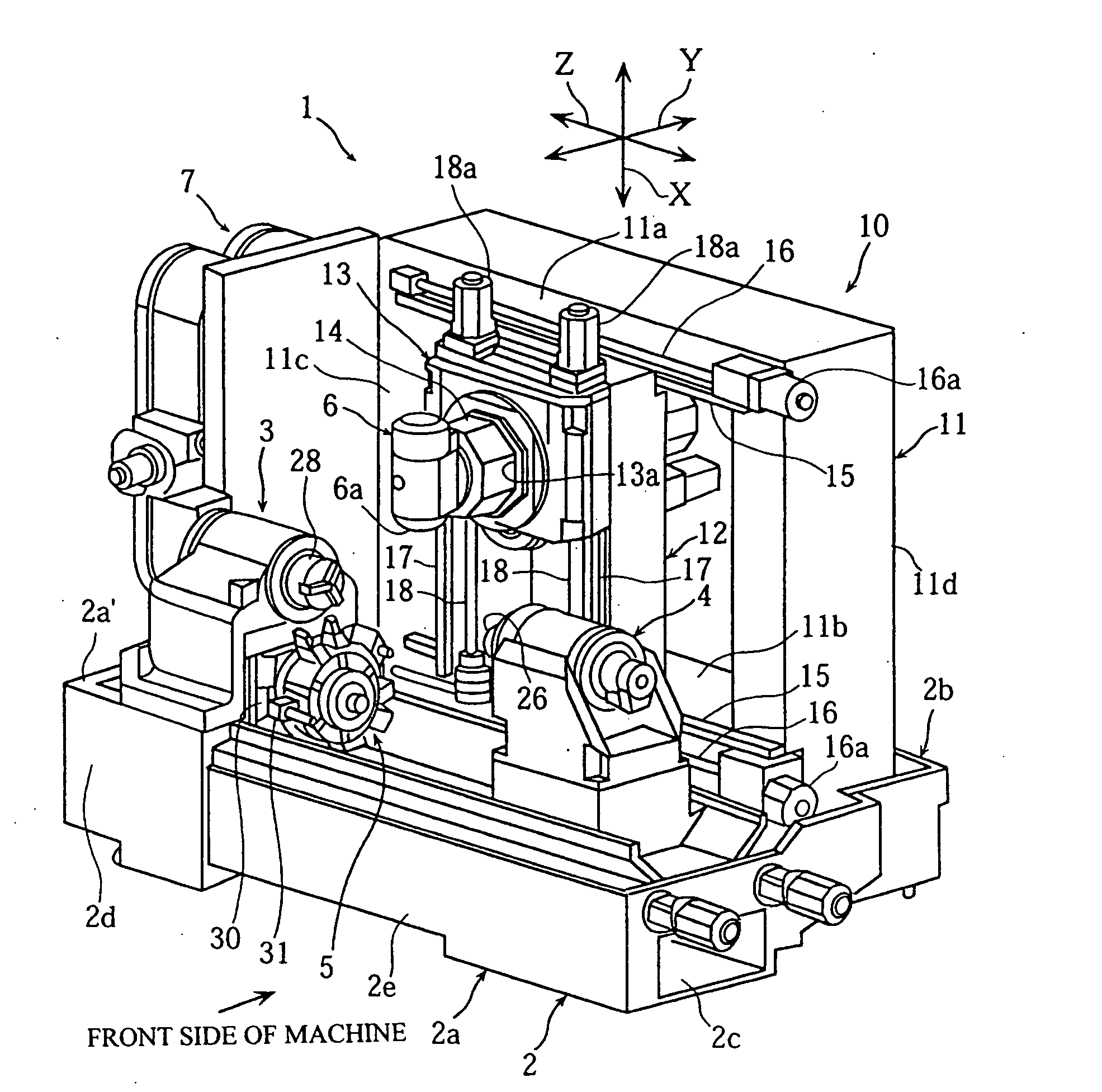
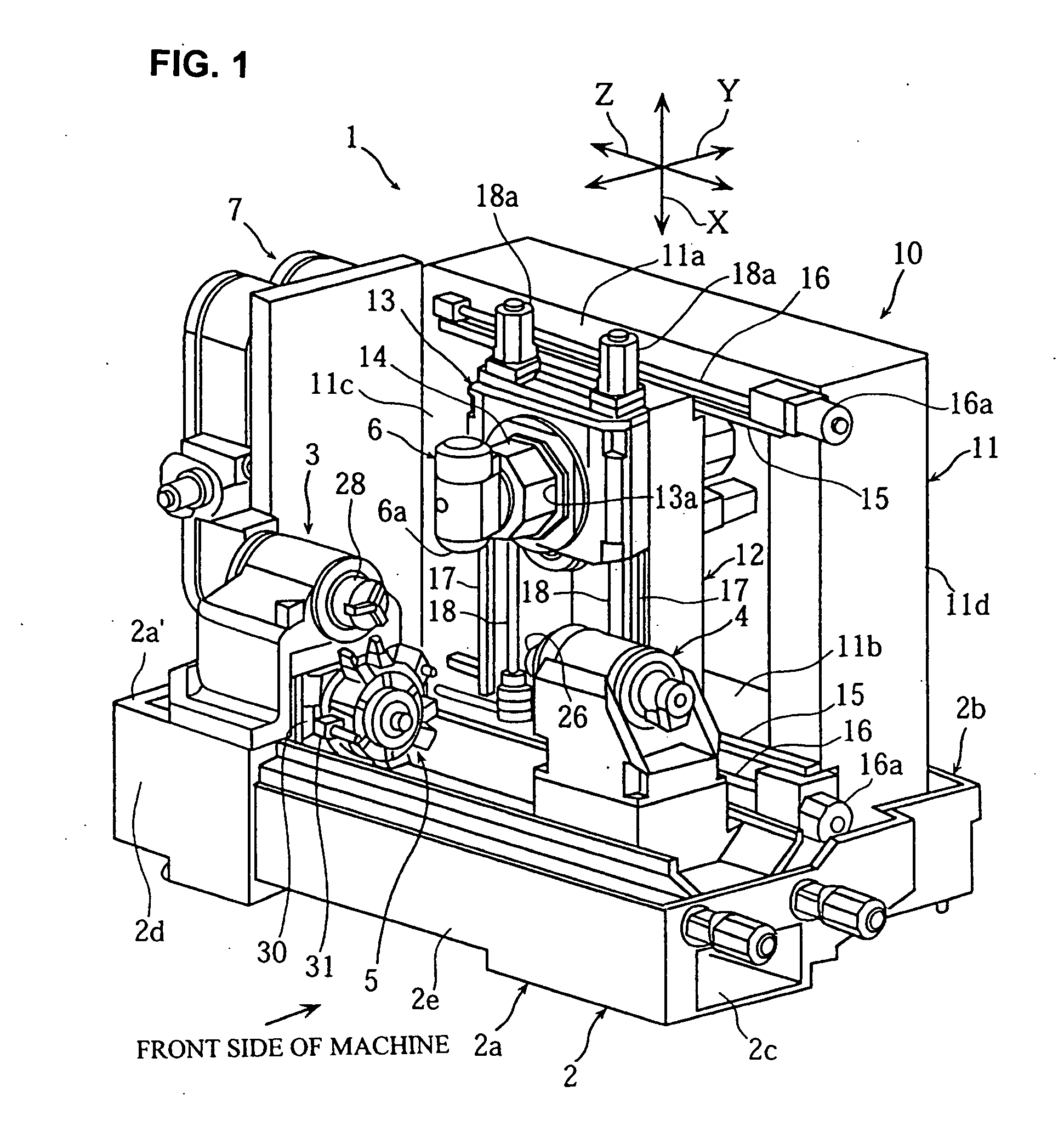
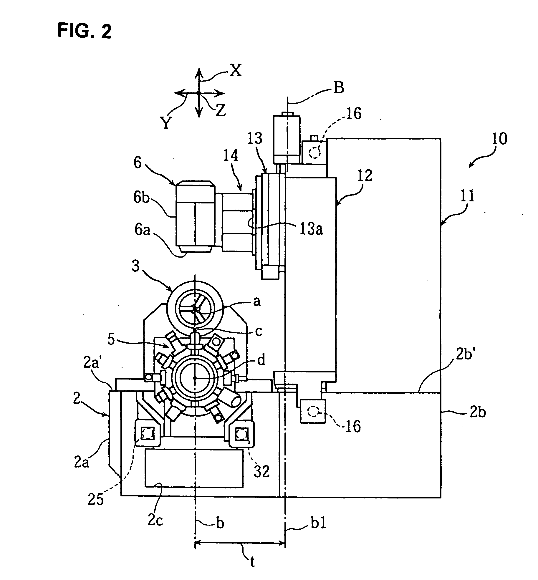
[0043]FIG. 1 to FIG. 18 are views to illustrate a composite lathe according to one embodiment of the present invention. FIG. 1 and FIG. 2 are a perspective view and a right side view of the composite lathe respectively, FIG. 3 and FIG. 4 are perspective views of a bed on which a first spindle headstock and a tool post are mounted, FIG. 5 is a front view of a supporting mechanism supporting a third spindle, FIG. 6 is a right side view of the first spindle headstock and the tool post, FIG. 7(a) to FIG. 7(c) are front views showing operations of the first spindle headstock, a second spindle headstock, and the tool post, FIG. 8 to FIGS. 11(a), (b) are views of the first spindle headstock, FIG. 12 is a perspective view of a cooling oil jacket of the first spindle headstock, FIG. 13 to FIG. 16 are views of the tool post, and FIG. 17 and FIG. 18 are views showing X-axis and Y-axis di...


PUM

PropertyMeasurementUnit
symmetryaaaaaaaaaa
dimensionaaaaaaaaaa
shapeaaaaaaaaaa

Abstract

To provide a machine tool in which a workpiece can be delivered to/from a first and a second spindle headstock without any increase in front/back direction dimension of a machine main body. A second spindle headstock 4 is capable of moving to a position for workpiece delivery to/from a first spindle headstock 3 so as to be close to or to abut on the first spindle headstock 3. When the second spindle headstock 4 is positioned at the workpiece delivery position, a tool post 5 is positioned right under the first spindle headstock 3 so that its cutting point “c” is positioned vertically under an axis “a” of the first and second spindle headstocks 3, 4.

Description

BACKGROUND OF THE INVENTION [0001] 1. Field of the Invention [0002] The present invention relates to a machine tool including: a first and a second spindle headstock disposed on a bed; and a tool post disposed between the first and second spindle headstocks. [0003] 2. Description of the Related Art [0004] An example of a machine tool of this type is structured such that, when seen from a front side of the machine, a first spindle headstock is fixedly disposed on a left end portion of a bed, a second spindle headstock is disposed on a right side to be movable in a Z-axis direction, and an upper tool post and a lower tool post are disposed between the first and second spindle headstocks to be movable in the Z-axis direction and an X-axis direction (see, for example, FIG. 4 of Patent document 1). In this machine tool, a workpiece having been subjected to predetermined machining by the first spindle headstock is transferred and attached to the second spindle headstock by a workpiece del...

Claims


Application Information

Patent Timeline
Patent Type & Authority Applications(United States)
IPC IPC(8): B23P23/00
CPCB23Q39/028B23Q2230/006B23Q2039/008Y10T82/2524Y10T29/5114Y10T82/2508Y10T82/2552B23Q2039/004
Inventor HASHIMOTO, HIROSHITSUCHIYA, HIROYUKITOKUMA, TSUTOMU
Owner DMG MORI SEIKI CO LTD
Why Eureka
Try Eureka