Partial tooth gear bearings

a technology of gear bearings and teeth, applied in the field of gear bearings, can solve problems such as marginally less efficient anti-backlash planetary transmissions

Inactive Publication Date: 2006-10-05
NASA
View PDF12 Cites 13 Cited by
  • Summary
  • Abstract
  • Description
  • Claims
  • Application Information

AI Technical Summary

Problems solved by technology

It is marginally less efficient than the anti-backlas

Method used


Image

  • Partial tooth gear bearings
  • Partial tooth gear bearings
  • Partial tooth gear bearings

Examples


Embodiment Construction

[0045] Reference is now made to the drawings, in which like numbers are used to designate like features throughout. The general purpose of this invention is to significantly improve off-the-shelf roller bearing system performance capabilities in a cost-effective manner. Due to the large numbers of traditional roller bearing systems in existence and due to the simplicity and low cost of the add-ons and, finally, due to the amount of performance improvement experienced, this invention represents a significant improvement in the art of gear bearings.

Half Tooth Gear Bearing Construction

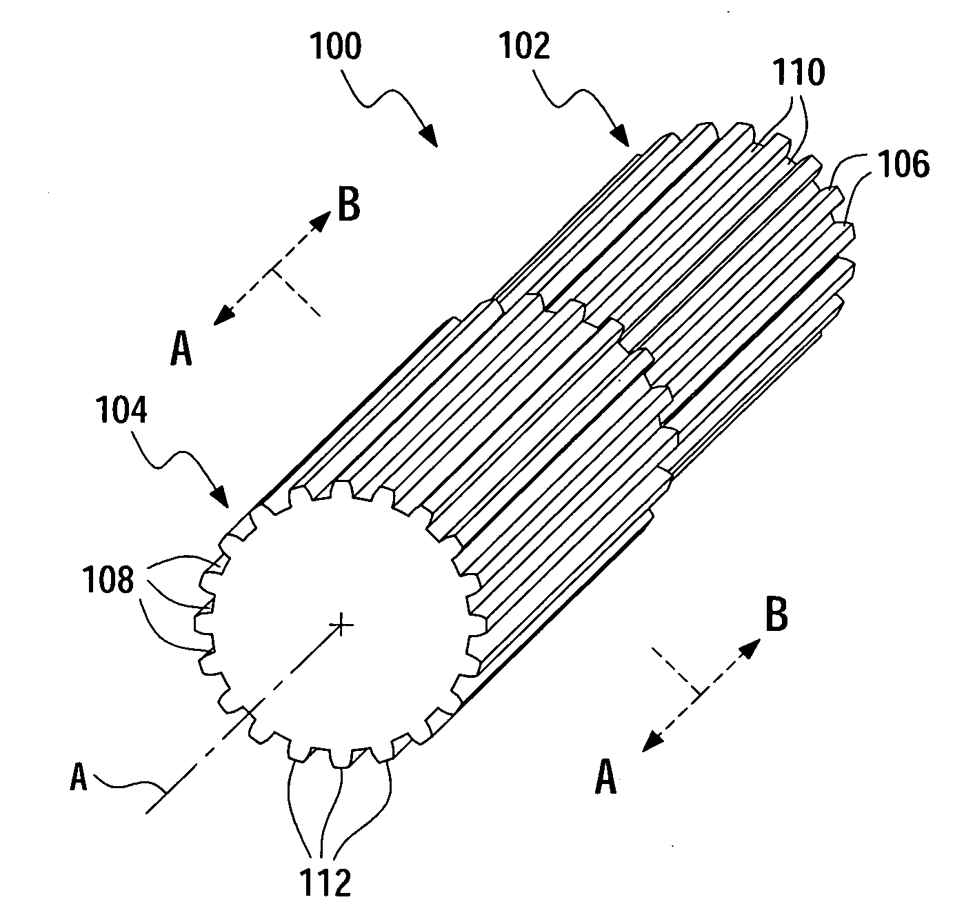
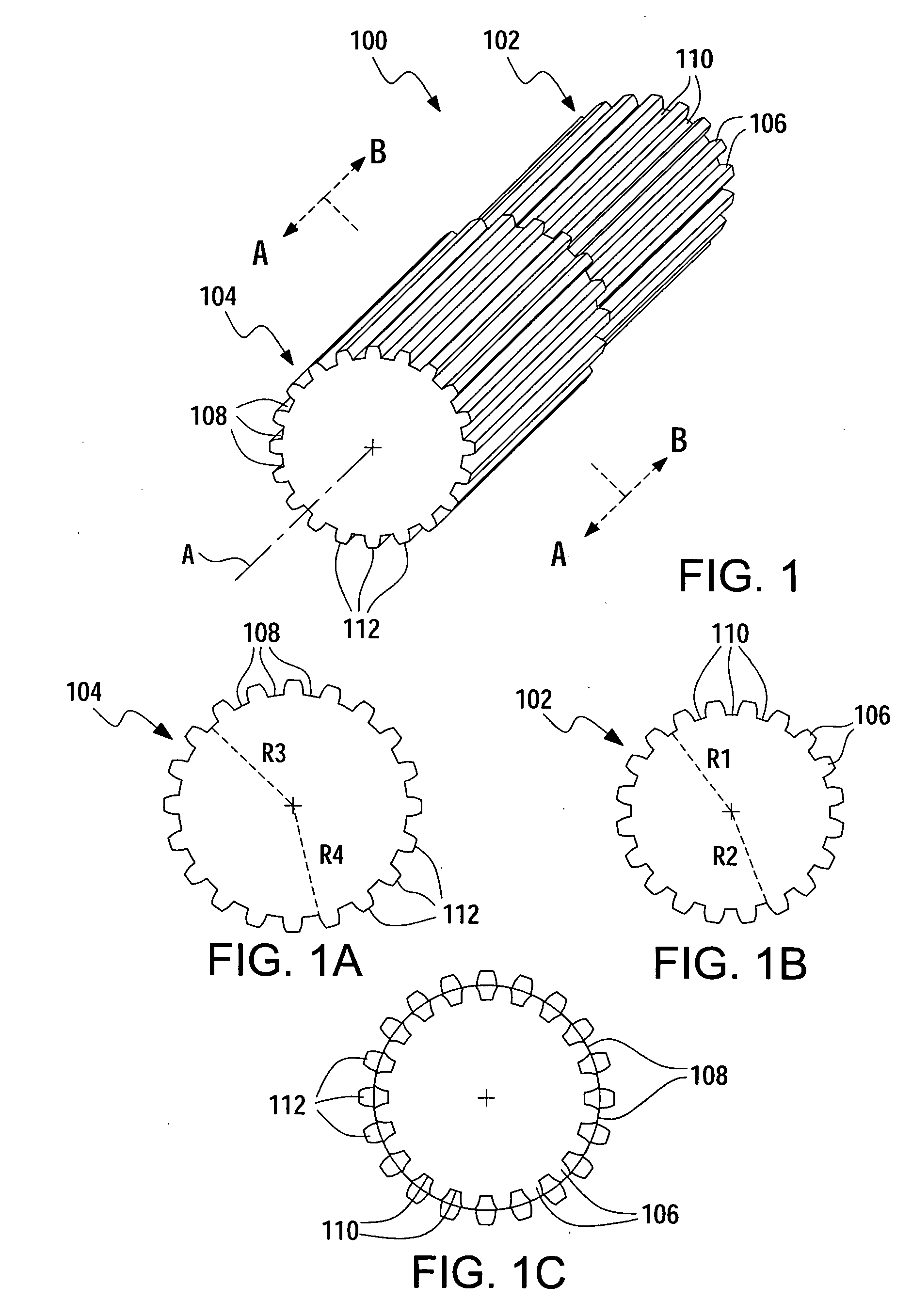
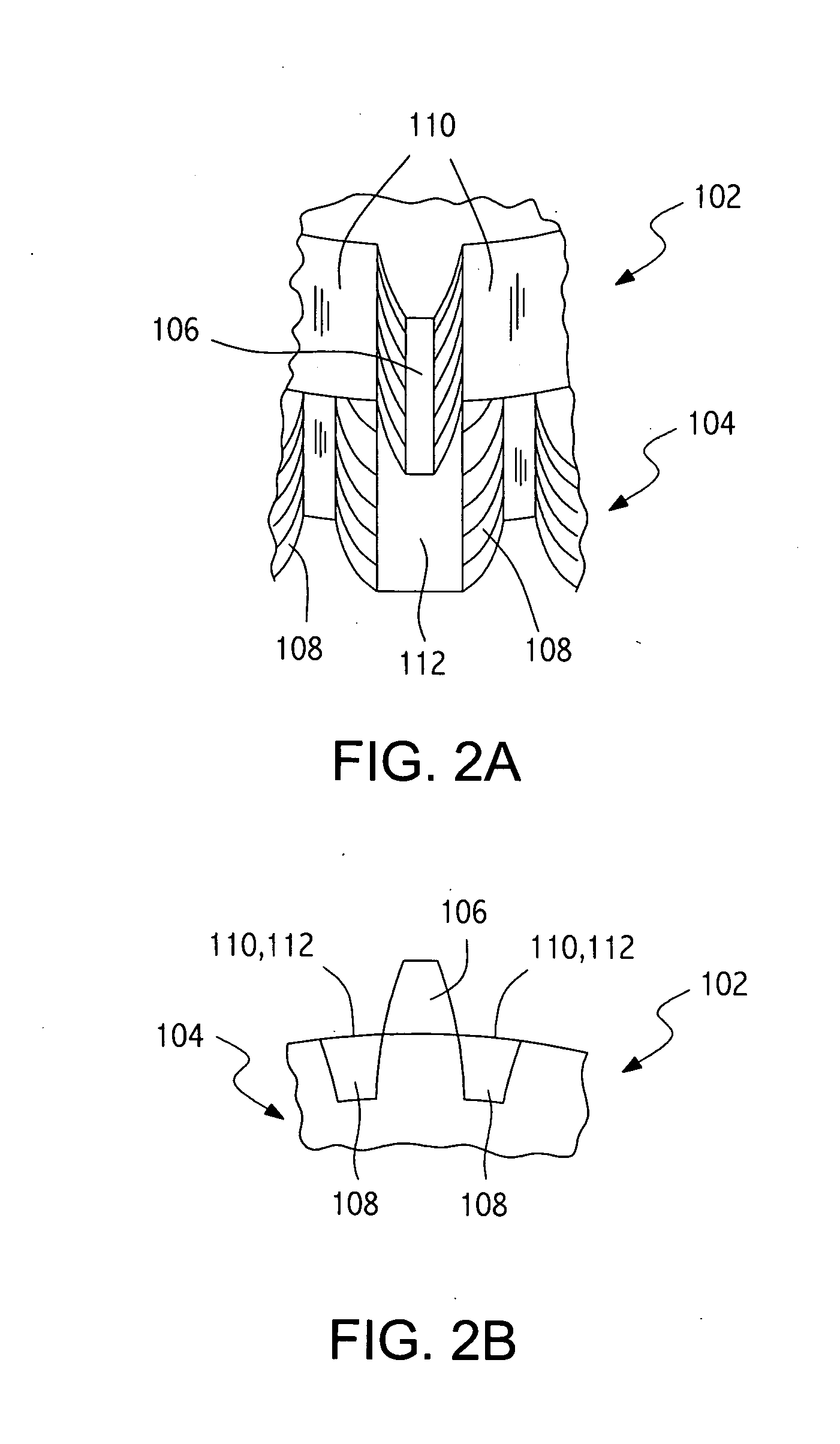
[0046] A preferred embodiment of a spur partial tooth gear bearing 100 (see FIGS. 1, 1A through 1C, and 2) includes an upper half 102, comprising peak partial teeth 106, and a bottom or lower half 104, comprising valley partial teeth 108. The upper half 102 with peak partial teeth 106 has a roller section 110 integrally disposed between each of the peak teeth 106, the radius R1 of which is the same as ...


PUM


Abstract

This invention obviates the need for an end roller in the traditional gear bearing design without giving up the desired bearing functions. The preferred embodiment of the partial gear bearing of the invention includes an upper half, comprising peak partial teeth, and a lower, or bottom, half, comprising valley partial teeth. The upper half also has an integrated roller section between each of the peak partial teeth with a radius equal to the gear pitch radius of the radially outwardly extending peak partial teeth. Conversely, the lower half has an integrated roller section between each of the valley half teeth with a radius also equal to the gear pitch radius of the peak partial teeth. The valley partial teeth extend radially inwardly from its roller section. The peak and valley partial teeth are exactly out of phase with each other, as are the roller sections of the upper and lower halves. Essentially, the end roller bearing of the typical gear bearing has been integrated into the normal gear tooth pattern.

Description

CROSS-REFERENCE TO RELATED APPLICATIONS [0001] This application is a continuation of co-pending patent application Ser. No. 10 / 789,031, filed on Feb. 26, 2004, which formalizes and incorporates by reference Provisional Application Ser. No. 60 / 453,338, “Half Tooth Gear Bearings,” John M. Vranish, filed on Feb. 27, 2003. Applicant hereby claims the priority date of Feb. 27, 2003 under 35 U.S.C. 119(e).ORIGIN OF THE INVENTION [0002] This invention was made by an employee of the United States Government and may be used by or for the Government for governmental purposes without the payment of any royalties thereon or therefor. BACKGROUND OF THE INVENTION [0003] 1. Field of Invention [0004] This invention relates generally to the field of gear bearings and more specifically to a novel, inexpensive approach to distribute non-axial forces applied to a gear bearing without the use of a separate roller. [0005] 2. Background of the Invention [0006] Gear bearings have become known in the art. S...

Claims


Application Information

Patent Timeline
IPC IPC(8): F16H55/00
CPCF16H57/02004Y10T74/19972Y10T74/19651Y10T74/19623
Inventor VRANISH, JOHN M.
Owner NASA
Why Eureka
Try Eureka