
Real time dynamically controled elevation and azimuth gun pod mounted on a fixed wing aerial combat vehicle

a dynamic control and elevation technology, applied in the field of gun pods, can solve problems such as gun deflection, and achieve the effect of reducing the aerodynamic efficiency and stability of the aircraft and reducing the degradation of the aerodynamic efficiency

Inactive Publication Date: 2006-10-05
PADAN NIR
View PDF11 Cites 30 Cited by
  • Summary
  • Abstract
  • Description
  • Claims
  • Application Information

AI Technical Summary

Benefits of technology

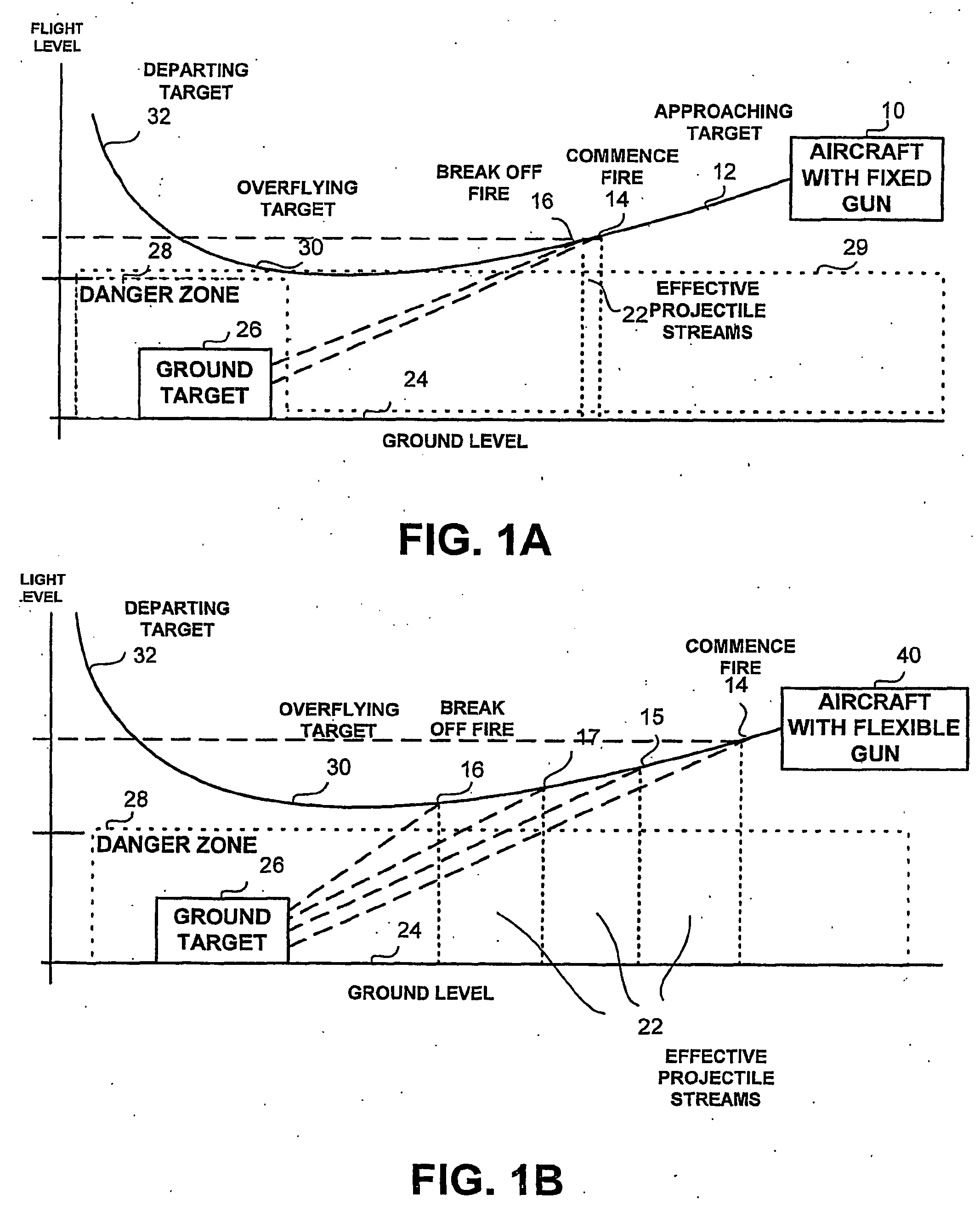
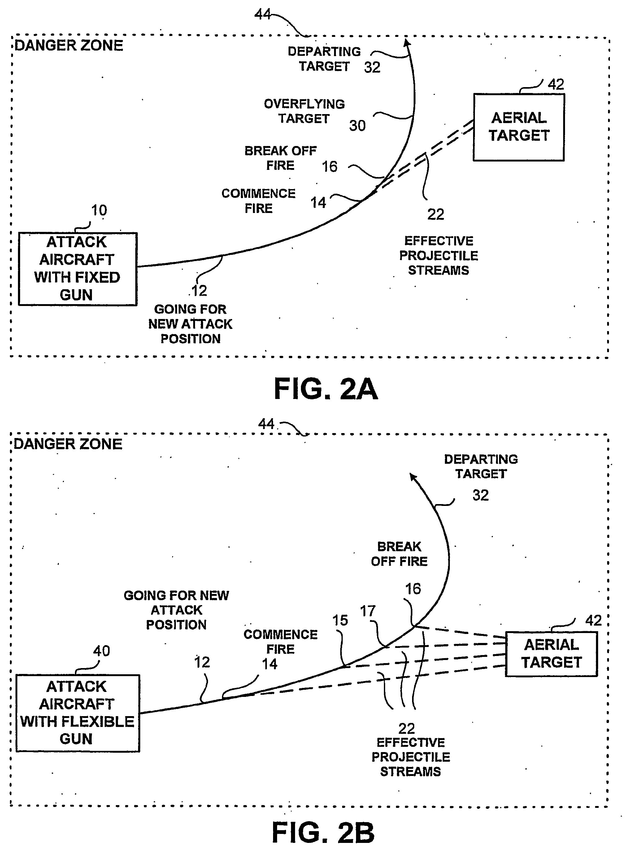
[0012] The present invention provides for a system and method of substantially automatic real-time slaving and positioning of a wide-angle aerial gun towards the target within a maximum allowable deflection capacity that is either fixed deflection pre-defined limited, or by a fire control system allows changing deflection variant limit as a function of pod type, carrier aircraft, weapon station that carry the pod, airspeed, angle of attack ext., suitable for a rapidly changing environment with minimum degradation of the aerodynamic efficiency and the stability of then aircraft.
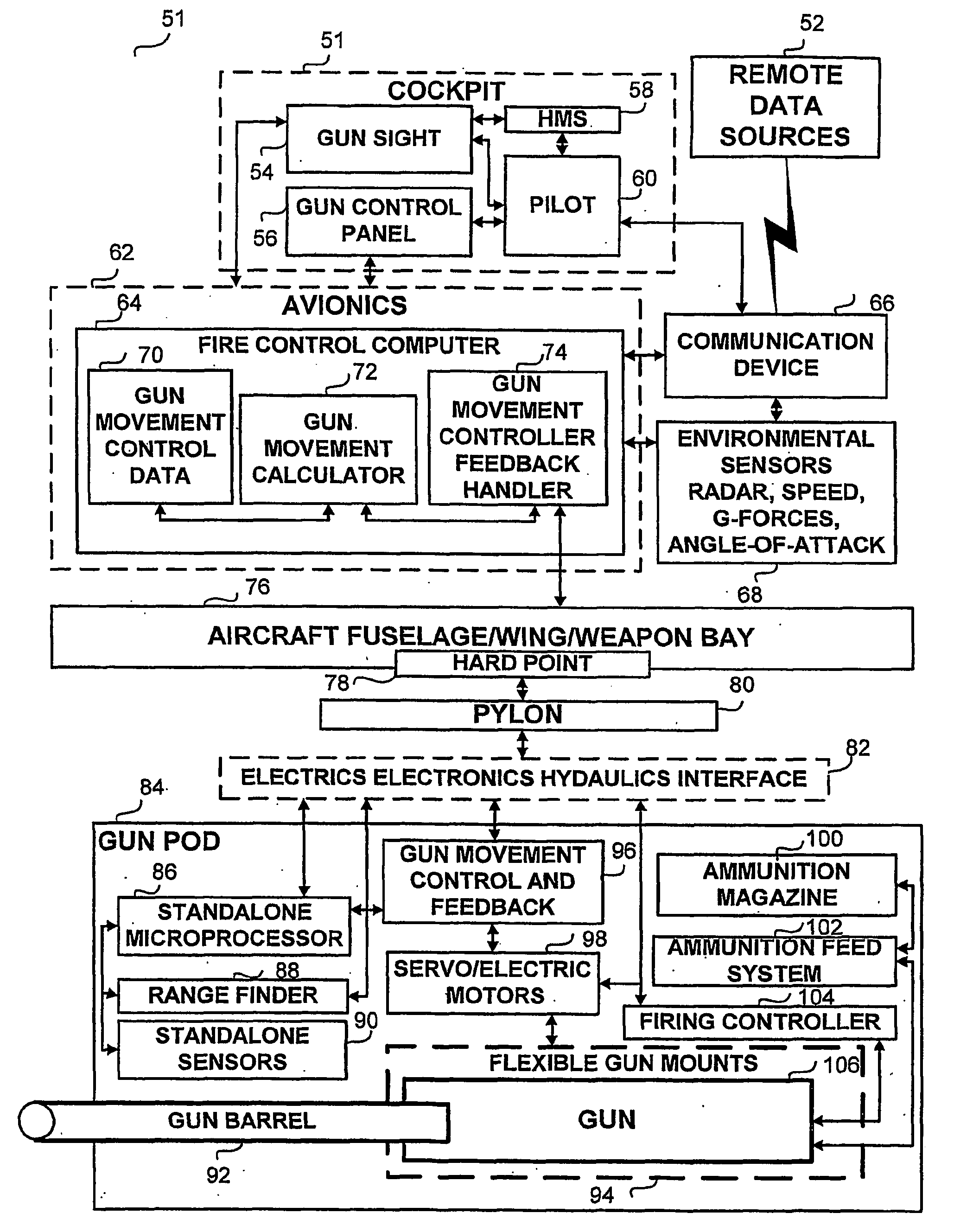
[0014] A second aspect of the present invention regards a method for dynamically controlling the elevation and azimuth of an aerial gun unit incorporated within a gun pod unit mountable on a fixed-wing aerial combat vehicle. The method comprises of the following steps: modifying the strength, diameter and volume of the gun pod unit to allow for the incorporation of the gun unit and gun movement support components, extending the diameter of the gun pod aperture to enable the allowable ranges of movement in the elevation and the azimuth for the barrels associated with the gun unit and installing an aerodynamic flexible covering on the gun pod aperture to provide for efficient air flow in the vicinity of the gun pod unit.

Problems solved by technology

Furthermore, the gun may have a deflection according to real time limitation such as when the gun is used by an aircraft having limited envelope or instruments, which will allow the full use of the gun's capabilities.

Method used


Image

  • Real time dynamically controled elevation and azimuth gun pod mounted on a fixed wing aerial combat vehicle
  • Real time dynamically controled elevation and azimuth gun pod mounted on a fixed wing aerial combat vehicle
  • Real time dynamically controled elevation and azimuth gun pod mounted on a fixed wing aerial combat vehicle

Examples


Embodiment Construction

[0023] The present invention discloses a novel gun pod to be mounted and integrated on a fixed-wing aerial combat vehicle. The present invention also discloses an apparatus and method for dynamic controlling of the elevation and azimuth of a wide-angle gun integrated into a gun pod mountable on a fixed-wing aerial combat vehicle. The gun pod includes one or more guns, standard gun support components, such as an ammunition magazine; ammunition feed sub-system, a monitoring sub-system, and a firing control sub-system. The gun is provided with the capability of movement across a range of deflection degrees relative to the axes of the aircraft. The gun mounted in the pod may be controlled and moved longitudinally and attitudinally (covers both). The pod is designed to allow such movement while the gun muzzle can is partially covered to allow better aerodynamic shape to the pod thus allowing the plane to maintain envelope limitations when flying at various speeds angles of attack. The ae...


PUM


Abstract

A gun pod, mounted on a fixed-wing aerial vehicle, stores, delivers, controls and supports a controllable movement gun unit. The gun pod includes a flexible gun mount, gun movement actuators, gun movement controllers, a standalone range finder, a standalone processor, and standalone sensors for capturing dynamically environmental data and for controlling the movement of the gun unit. The gun is provided with allowable ranges of movement in the elevation and the azimuth where the ranges are determined in accordance with the flight envelope of the aerial vehicle, the characteristics of the gun unit and the mounting location of the gun pod. The movement of the gun is either controlled manually or automatically.

Description

BACKGROUND OF THE INVENTION [0001] 1. Field of the Invention [0002] The present invention generally relates to gun pods carried and utilized in aerial combat by fixed-wing military aerial vehicles. More particularly the present invention relates to gun pods, having the capability of controlling dynamically the elevation and the azimuth of an incorporated gun while being mounted on a fixed-wing aerial combat vehicle. [0003] 2. Discussion of the Related Art [0004] Although presently modern military combat aircraft are typically equipped with diverse highly sophisticated advanced weaponry, such as guided missiles and precision-guided bombs, aerial gun systems are still widely used as an important component of an aircraft's weapon configuration both for Air-to-Air (A / A) and for Air-to-Ground (A / G) operations. Gun systems are versatile, reliable, lethal and low cost solution. Thus, the majority of fixed-wing military combat aircraft and attack helicopters are provided with the option of ...

Claims


Application Information

Patent Timeline
Patent Type & Authority Applications(United States)
IPC IPC(8): F41A23/00B64D7/06
CPCB64D7/06F41A27/02F41G5/18F41A27/28F41A27/30F41A27/06
Inventor PADAN, NIR
Owner PADAN NIR
Learn More