Counterbalanced deck for railroad freight car

a rail freight car and counterbalance technology, applied in the direction of railway bodies, axle-box lubrication, wagons/vans, etc., can solve the problems of heavy deck and many operators' difficulty in raising and lowering, and achieve the effect of lightening the weigh

Inactive Publication Date: 2006-10-05
GUNDERSON
View PDF44 Cites 23 Cited by
  • Summary
  • Abstract
  • Description
  • Claims
  • Application Information

AI Technical Summary

Benefits of technology

[0008] The present invention overcomes the aforementioned shortcomings of prior art railroad cars for carrying motor vehicles on multiple levels and meets the aforementioned needs by providing an improved car body including a motor vehicle deck spaced upwardly above a lowest load carrying floor, and provides a movable end portion of such a deck which is significantly lighter in weight than previously known movable end portions for such railroad freight cars.
[0009] In a preferred embodiment of the invention, one or more deck-supporting counterbalance mechanisms, each including a spring, are arranged to partially support the weight of the movable end portion as it is being raised or lowered. The disclosed counterbalance mechanism has an elongate tension-carrying member coupled to the movable end portion of the deck for applying a lifting force from a spring to enable the movable end portion of the deck to be raised with mere hand pressure. The lifting force provided by the counterbalance mechanism assists the persons raising the movable end portion of the deck by carrying most of its weight as it is moved between its raised and lowered positions.
[0012] In a preferred embodiment of the invention, the movable end portion of a deck is of a lightweight composite sandwich construction with top and bottom skins of fiber reinforced plastic resin and with a core of low density material.
[0014] In a preferred embodiment, the deck has a shape that provides ample strength for supporting motor vehicles, but also provides ample space to accommodate motor vehicles of various heights that the car is intended to carry.

Problems solved by technology

The deck is heavy, and many operators have difficulty raising and lowering it with only a manually operated mechanical winch.

Method used


Image

  • Counterbalanced deck for railroad freight car
  • Counterbalanced deck for railroad freight car
  • Counterbalanced deck for railroad freight car

Examples


Embodiment Construction

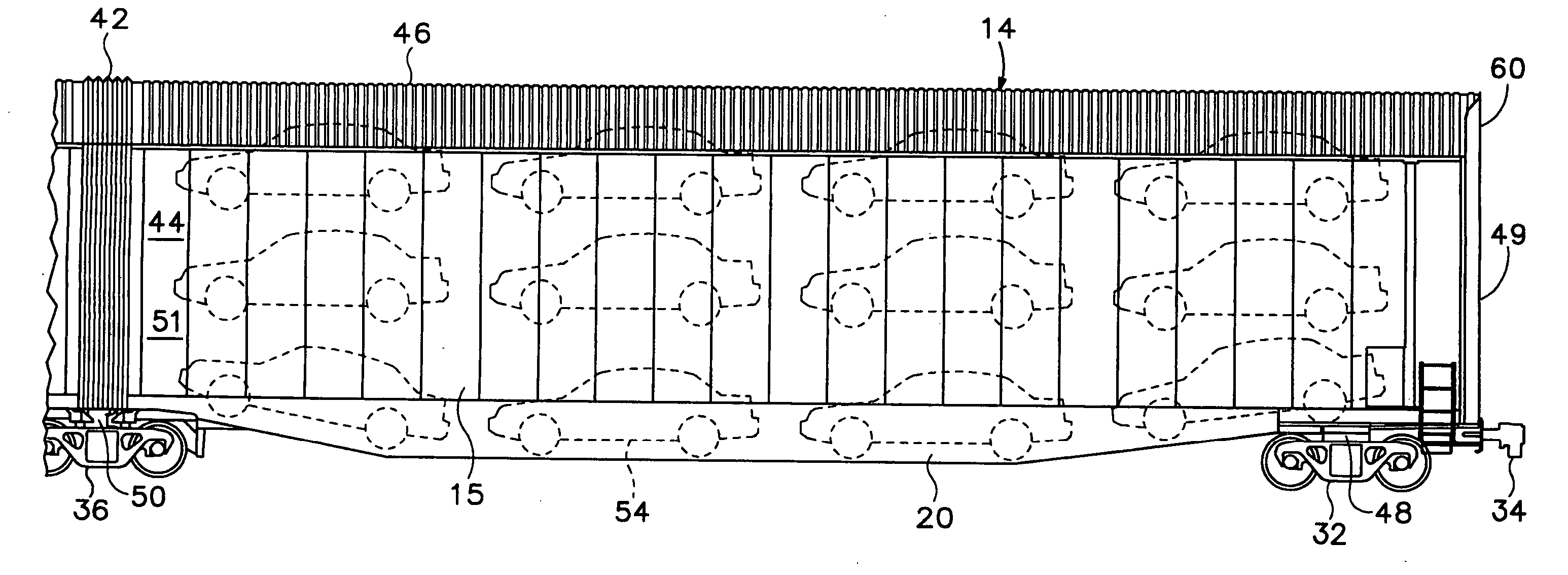
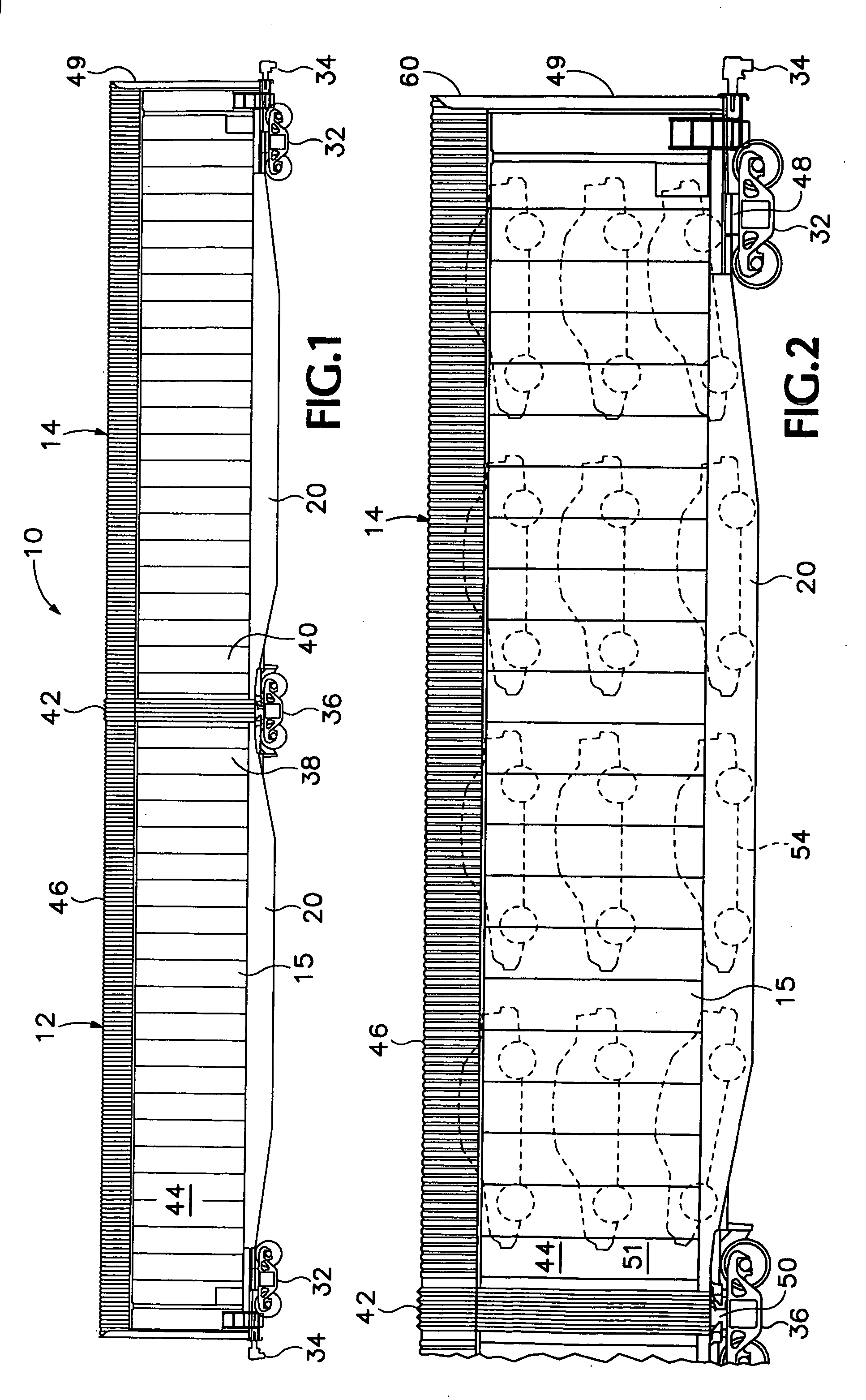
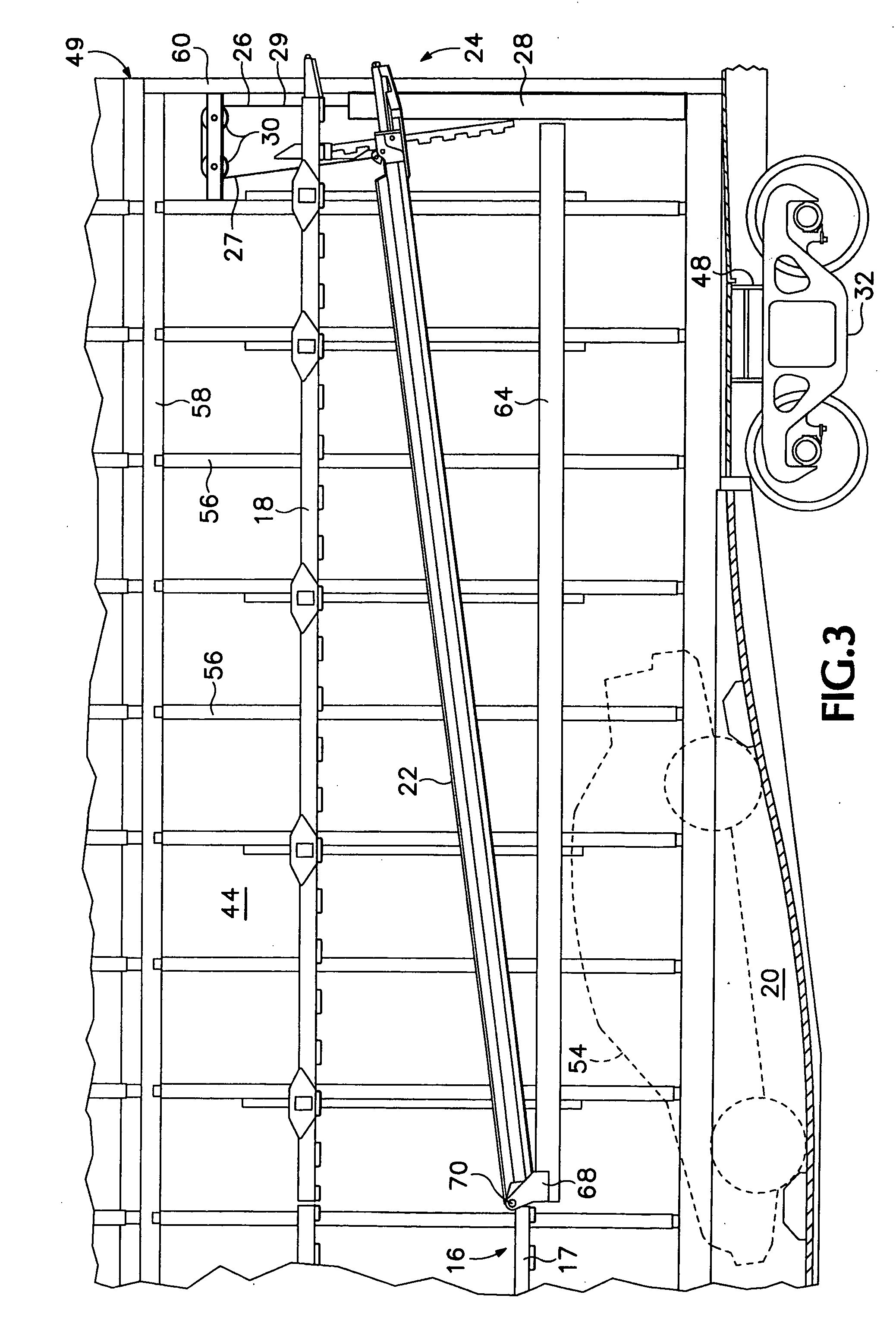
[0032] Referring to the drawings, which form a part of the disclosure herein, FIGS. 1-4 show a multi-unit railroad freight car 10 that incorporates one preferred embodiment of the present invention. The freight car 10 includes two adjacent car units 12 and 14. Each respective car unit 12 and 14, in turn, includes a cargo well 20, a middle deck 16, and an upper deck 18 for selectively supporting and storing automobiles in a tri-level arrangement as shown in FIG. 2. The cargo well 20, the middle deck 16, and the upper deck 18 are sometimes referred to as the “A”, “B”, and “C” decks, respectively. Each deck 16, 18, and 20 preferably has a shape that provides ample strength for supporting motor vehicles, while providing sufficient space to accommodate motor vehicles of the various heights that the car is desired to carry.

[0033] As can be seen in FIGS. 2-3, the automobiles stored on the lowest level of the freight car 10 rest in the respective cargo well 20 of each car unit 12 and 14. I...


PUM


Abstract

A railroad car includes a body having a pair of side walls and at least a pair of parallel horizontal support beams extending along the side walls at substantially the same height. A movable end portion of a deck built as a lightweight composite structure may pivot with respect to the pair of support beams. A respective counterbalance apparatus is arranged between each of the pair of side walls and the movable deck portion at a location spaced apart from the pivot axis so as to provide a lifting force acting on the movable end portion to urge it to pivot upward about the pivot axis.

Description

CROSS-REFERENCE TO RELATED APPLICATIONS [0001] This is a continuation of patent application Ser. No. 10 / 401,153, filed on Mar. 27, 2003, which is hereby incorporated by reference.BACKGROUND OF THE INVENTION [0002] The present invention relates to railroad freight cars and in particular to a freight car for carrying motor vehicles on multiple levels. [0003] Railroad freight cars have long been used for transporting newly manufactured automobiles long distances from either the place of manufacture or a port of arrival to a place where the automobiles are reloaded onto trucks that deliver the automobiles to dealerships. In order for such railroad freight cars to be most economical it is desirable to carry a maximum number of motor vehicles on each railroad car, but it is also desired to be able to carry several different types of motor vehicles on each car and to be able to reconfigure the railroad freight car to carry such different types of vehicles without undue difficulty. [0004] U...

Claims


Application Information

Patent Timeline
Patent Type & Authority Applications(United States)
IPC IPC(8): B61D17/00B61D3/18
CPCB61D3/187
Inventor JARVIS, JAMES J.
Owner GUNDERSON
Why Eureka
Try Eureka