Floating blade apparatus for cutting concrete

a technology of concrete and blades, applied in the field of concrete, can solve the problems of general failure to provide concrete cutting equipment, etc., and achieve the effect of reducing or dampening vibration

Inactive Publication Date: 2006-10-05
ZHANG CHARLIE
View PDF3 Cites 3 Cited by
  • Summary
  • Abstract
  • Description
  • Claims
  • Application Information

AI Technical Summary

Benefits of technology

[0016] A motor is fixedly connected with the body frame. The motor is in operational communication with the rotatable cutting blade and is effective to rotate the cutting blade to cut into the surface of concrete over which the apparatus is conveyed. The motor is also in operational communication with the conveyance system whereby the

Problems solved by technology

The prior art generally fails to provide an apparatus for cutting concrete, particularly green concrete, and which apparatus desirably facilitates or better ensures that the resu

Method used


Image

  • Floating blade apparatus for cutting concrete
  • Floating blade apparatus for cutting concrete
  • Floating blade apparatus for cutting concrete

Examples


Embodiment Construction

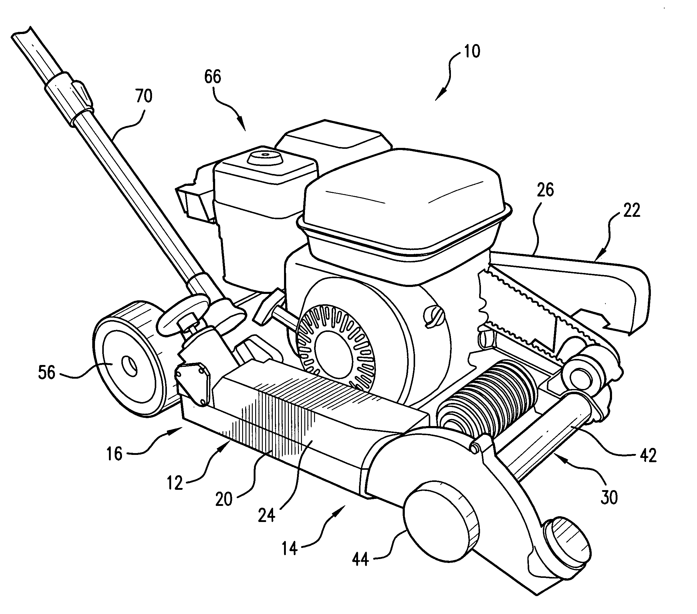
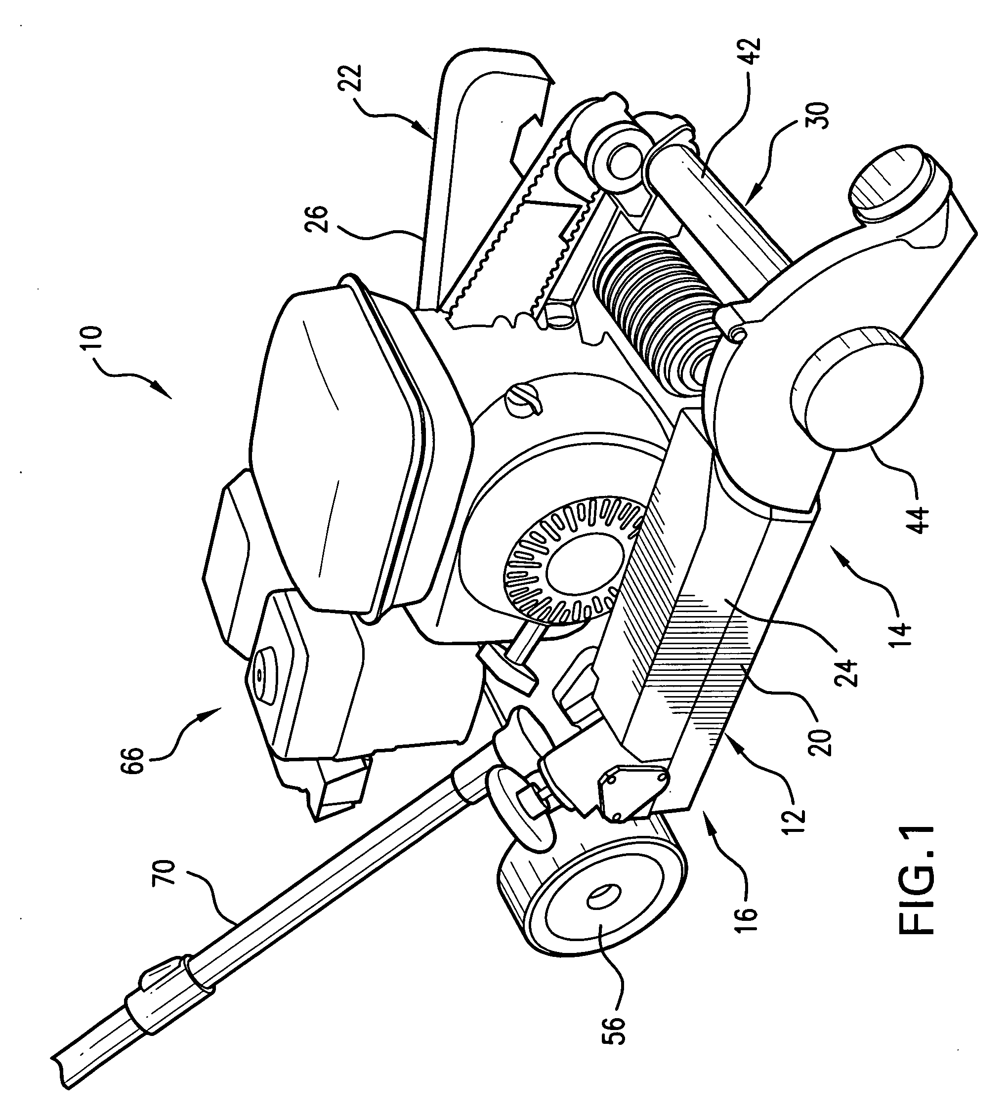
[0024] The present invention provides a floating blade apparatus particularly suited for cutting “green” or not fully cured concrete.

[0025] Turning to FIG. 1, there is illustrated a floating blade, concrete cutting apparatus, generally designated by the reference numeral 10, in accordance with one preferred embodiment of the invention. The floating blade, concrete cutting apparatus 10 generally includes a body frame 12. The body frame 12 has a lead or forward end 14 and a trail or rear end 16 that are generally opposed and spaced apart from each other. The body frame 12 also has opposed and spaced apart first and second lateral sides, 20 and 22, respectively. As shown, the apparatus 10 may desirably include side coverings, individually designated 24 and 26, generally disposed at or along the first and second lateral sides 20 and 22, respectively.

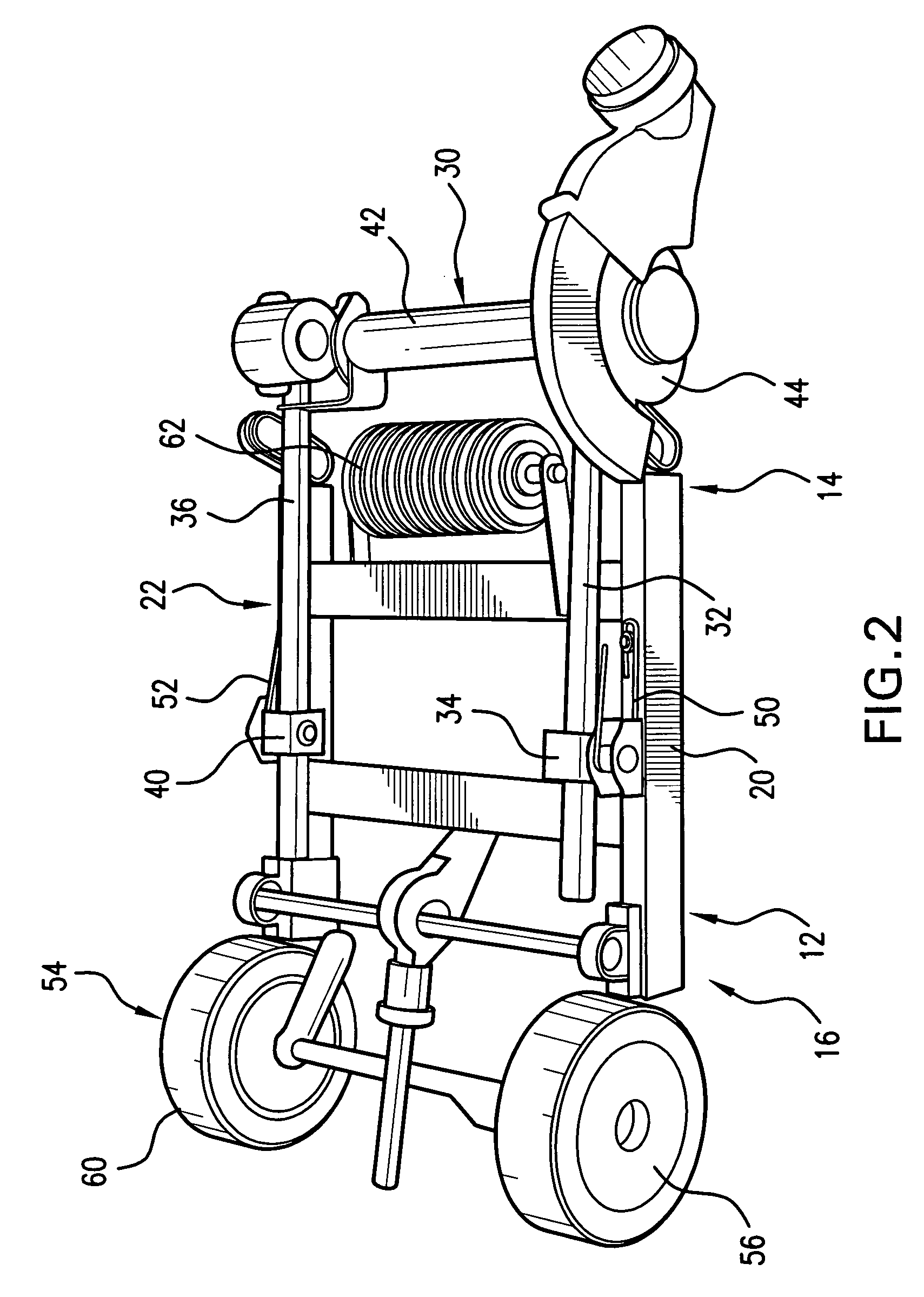
[0026] As perhaps best viewed by reference to FIG. 2, wherein covering components such as the side coverings 24 and 26 have been removed,...


PUM


Abstract

A floating blade apparatus for cutting a surface of concrete, particularly, green concrete. The apparatus includes a body frame and a cutting blade support frame operationally connected with the body frame. The cutting blade support frame relatively freely permitting a range of movement of a rotatable cutting blade relative to the surface of concrete over which the apparatus is conveyed. The apparatus may also include conventional features such as a conveyance system, a motor and a handle.

Description

BACKGROUND OF THE INVENTION [0001] This invention relates generally to concrete and, more particularly, to an apparatus for cutting concrete. More specifically, the invention relates to a concrete cutting apparatus particularly suited for cutting “green” or not fully cured concrete and which apparatus, as more fully described below, incorporates or utilizes a floating blade. [0002] The surfaces of large slabs of concrete are known to be prone to cracking such as may occur as a result of expansion and contraction as the slab of concrete cures. Such expansion and contraction of a concrete slab are typically dependent on numerous factors. In view thereof, various techniques or approaches for avoiding, reducing or otherwise effectively controlling such cracking have been proposed or developed. One commonly employed approach for avoiding, reducing or otherwise effectively controlling such cracking is through the introduction of control joints or seams in the surface of the concrete as th...

Claims


Application Information

Patent Timeline
IPC IPC(8): B28D1/04
CPCB28D1/18B28D1/042
Inventor ZHANG, CHARLIE
Owner ZHANG CHARLIE
Why Eureka
Try Eureka