Hydrostatic transmission and power train for vehicle

a technology of transmission and power train, applied in the direction of fluid couplings, gearings, couplings, etc., can solve the problem of effectively limited distance between the second end of the pto shaft and the driving axle, and achieve the effect of easy change of output state and easy mode chang

Inactive Publication Date: 2006-12-19
ISHIMARU YOSHITAKA +2
View PDF19 Cites 20 Cited by
  • Summary
  • Abstract
  • Description
  • Claims
  • Application Information

AI Technical Summary

Benefits of technology

[0018]With the power train of the above arrangement, the speed change range available in the drive-power transmission path can easily be widened. Also, by replacing the transfer device with a different one, the specification of the power train can easily be modified. That is, merely mounting or dismounting the transfer device, or modifying the same achieves matching to various specifications of the vehicle.
[0020]With the power train having the above arrangement, the PTO shaft that takes off the drive power synchronized with the driving axle can be effectively prevented from interfering with the main speed change device. Thus, the drive-power transmission mechanism disposed on the downstream side of the PTO shaft can be relatively flexibly designed.
[0022]With the power train having the above arrangement, the PTO shaft can effectively be rotated in synchronization with the output shaft, while sharing in part the common parts between the drive-power transmission line for the PTO system and the drive-power transmission line for the vehicle run. Thus, the transfer device can be manufactured compact as compared with the arrangement that the PTO drive power is taken off through the output shaft of the transfer device.
[0024]The transfer device preferably includes a clutch member that is relatively non-rotatably and axially slidably supported on the driving shaft. The clutch member is adapted to selectively take a position enabling connection between the driving shaft and the idle gear, a position enabling connection between the driving shaft and the output shaft, and a neutral position between both the positions, enabling shutdown of the drive-power transmission from the driving shaft to the output shaft.
[0027]With the arrangement above, it is possible to easily change the outputting state of the PTO shaft. Specifically, through shifting operation of the slider, it is possible to easily change the mode of the PTO shaft between a mode enabling forced synchronization of the PTO shaft with the output shaft, a mode enabling shutdown of the drive power transmission from the output shaft to the PTO shaft when the PTO shaft rotates at a higher speed than the output shaft, and a mode enabling shutdown of the drive power transmission to the PTO shaft.

Problems solved by technology

Therefore, the variation in distance between the second end of the PTO shaft and the driving axle can be effectively limited, even if the distance between the driving axle and the HST is varied.

Method used


Image

  • Hydrostatic transmission and power train for vehicle
  • Hydrostatic transmission and power train for vehicle
  • Hydrostatic transmission and power train for vehicle

Examples


Embodiment Construction

[0052]Embodiments of the HST for the vehicle according to the present invention will be hereinafter described with reference to the accompanying drawings. This embodiment will be described by taking for example the case that the vehicle, to which the HST is applied, has a front axle serving as a main driving axle, and is provided on the front side of the vehicle body with a working device in the form of a mower with an elevation function

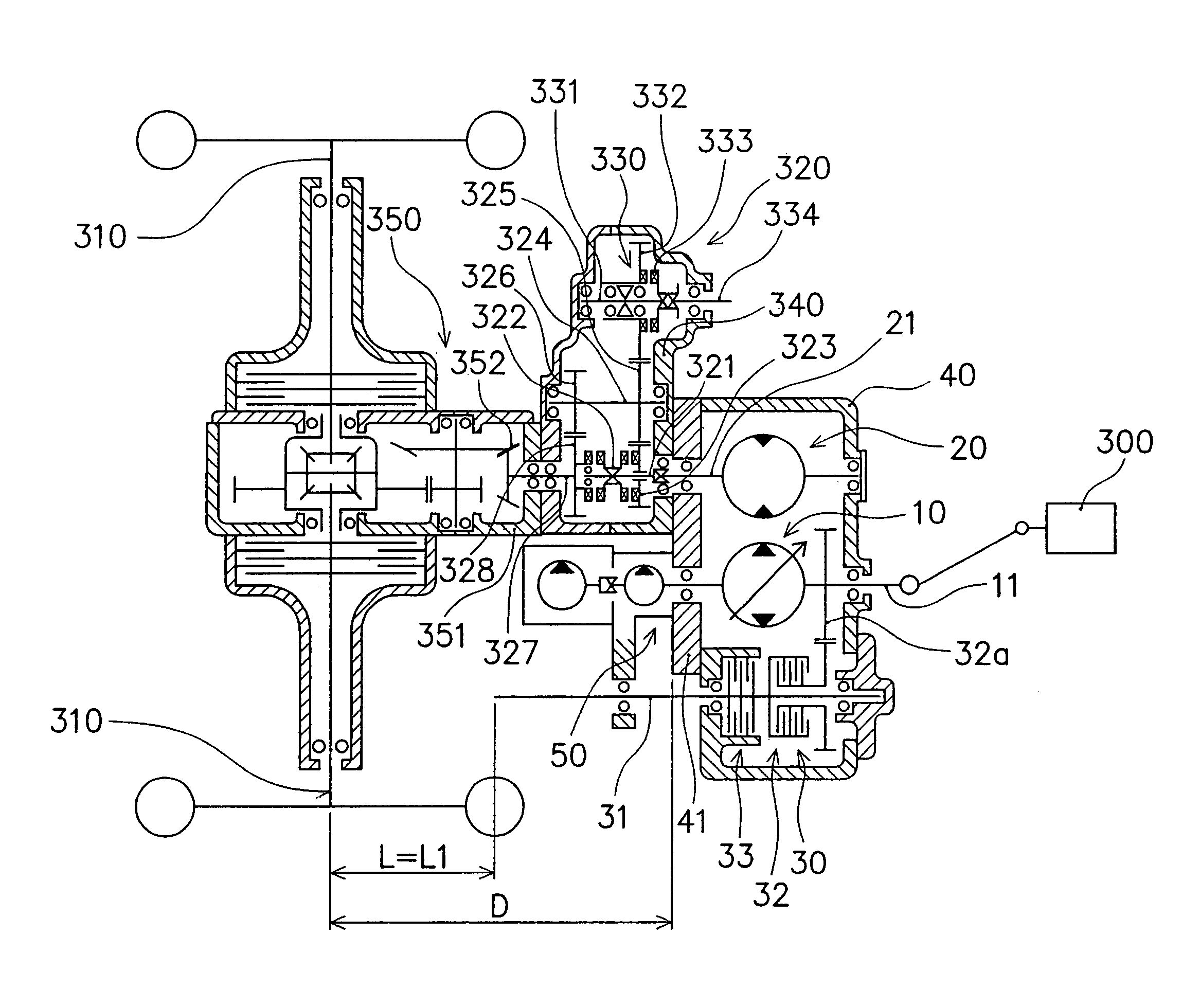
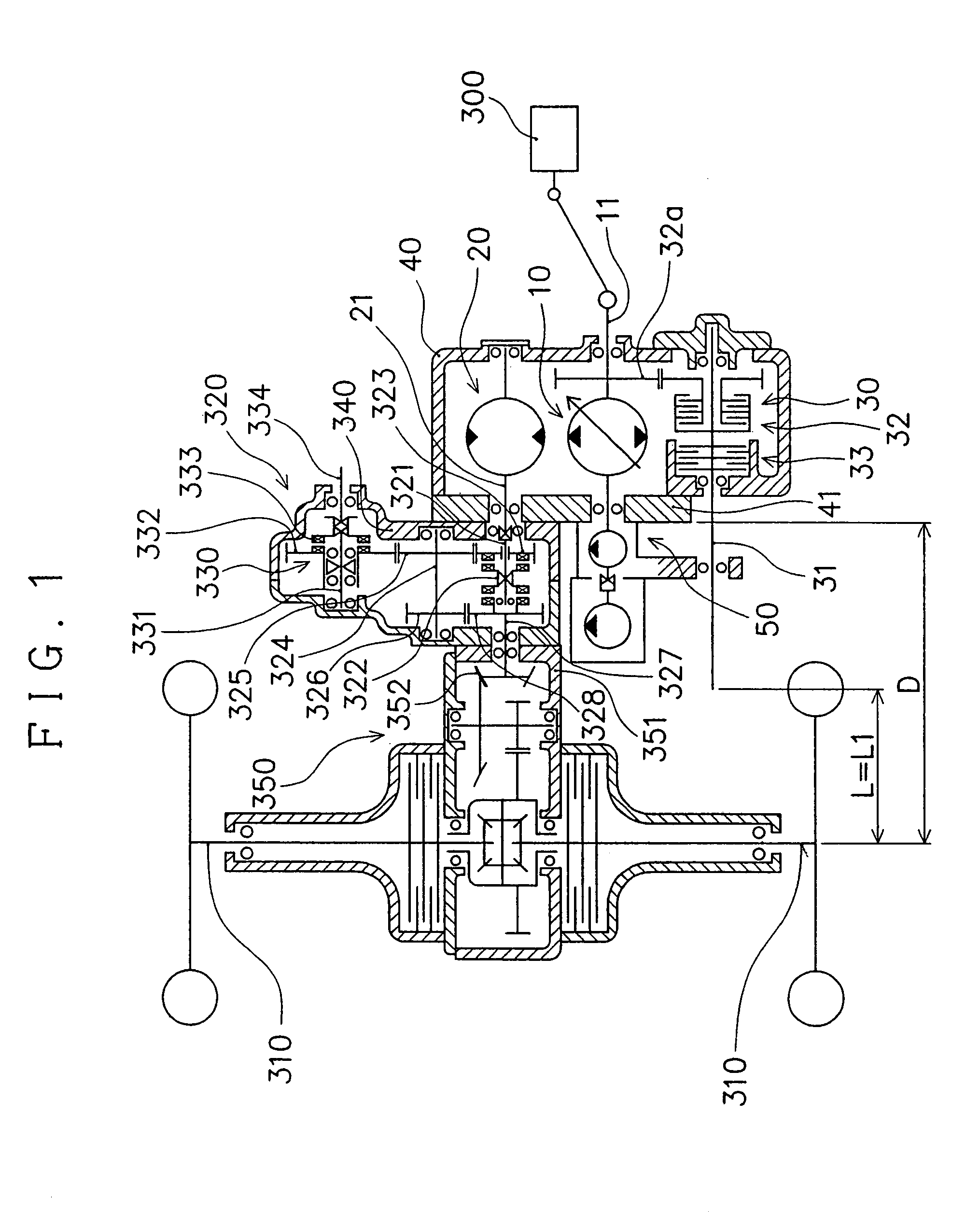
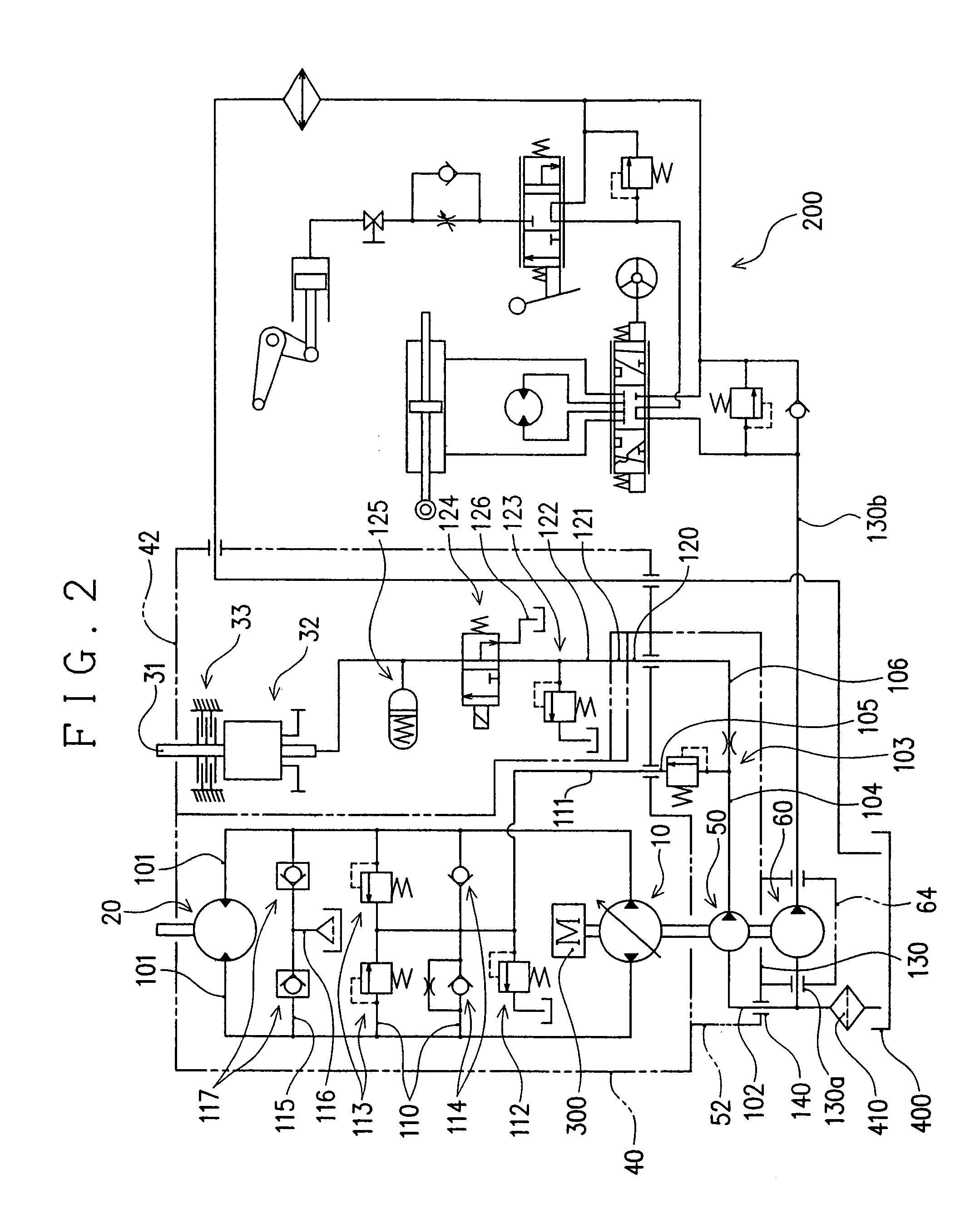
[0053]FIGS. 1 and 2 are respectively the power train model view and the hydraulic circuit diagram of the vehicle to which the HST is applied. FIG. 3 is the transverse plan view of the HST and FIG. 4 is the cross-section taken along lines IV—IV in FIG. 3.

[0054]As illustrated in those Figures, HST 1 is interposed in the drive-power transmission path between drive power source 300 and the driving axle (i.e., front axle 310 in this embodiment). That is, the HST 1 functions as one component of the power train for vehicle between power source 300 and the d...


PUM


Abstract

A hydrostatic transmission for vehicle interposed in a drive-power transmission path between a driving power source and a driving axle for non-stepwisely changing the speed of the vehicle includes an HST housing; a hydraulic pump unit having a pump shaft with first and second ends extending in a fore-aft direction of the vehicle away from each other; a hydraulic motor unit having a motor shaft for outputting the drive power from the motor shaft whose speed is non-stepwisely varied in cooperation with the hydraulic pump unit; a PTO unit having a PTO shaft extending in the fore-aft direction of the vehicle, the PTO shaft being operatively connected to the pump shaft; a charge pump unit for replenishing pressurized hydraulic fluid to a hydraulic circuit, the hydraulic circuit hydraulically connecting the hydraulic pump unit with the hydraulic motor unit, the charge pump unit including a charge pump body, and a charge pump case connected to the HST housing through its wall closer to the driving axle for supporting the charge pump body; the PTO shaft having an one end closer to the driving axle, the one end extending outwardly through the HST housing to have an outer extension positioned outside of the HST housing; and the charge pump case being designed so as to bearing-support the outer extension of the PTO shaft.

Description

BACKGROUND OF THE INVENTION[0001]The present invention relates to a hydrostatic transmission (hereinafter referred to as HST) for vehicle that is interposed in a drive-power transmission path between a drive power source and a driving axle, and a power train for vehicle between the drive power source and the driving axle.[0002]It is known that the HST interposed in the drive-power transmission path between the drive power source and the driving axle is provided with a PTO unit for driving a working device. FIG. 9(a) is a model view illustrating a drive-power transmission in the arrangement that a conventional HST with a PTO unit is applied to a vehicle that has a front axle serving as a driving axle and is provided on the front side of the, vehicle with a mower or any other working device.[0003]As illustrated in FIG. 9(a), the HST with the PTO unit includes a hydraulic pump unit with a pump shaft operatively connected to the drive power source, a hydraulic motor unit with a motor sh...

Claims


Application Information

Patent Timeline
Patent Type & Authority Patents(United States)
IPC IPC(8): F16H37/08B60K17/10B60K17/28F16H47/02F16H61/40F16H61/4139F16H61/42F16H61/437F16H61/448
CPCB60K17/105B60K17/28F16H47/02F16H61/40F16H61/4139F16H61/437F16H61/448F16H61/4026B60Y2200/223B60Y2200/41Y10T74/19116F16H61/42Y10T74/19084Y10T74/19219
Inventor ISHIMARU, YOSHITAKASAKIKAWA, SHIGENORISAKAKURA, SHINYA
Owner ISHIMARU YOSHITAKA
Why Eureka
Try Eureka