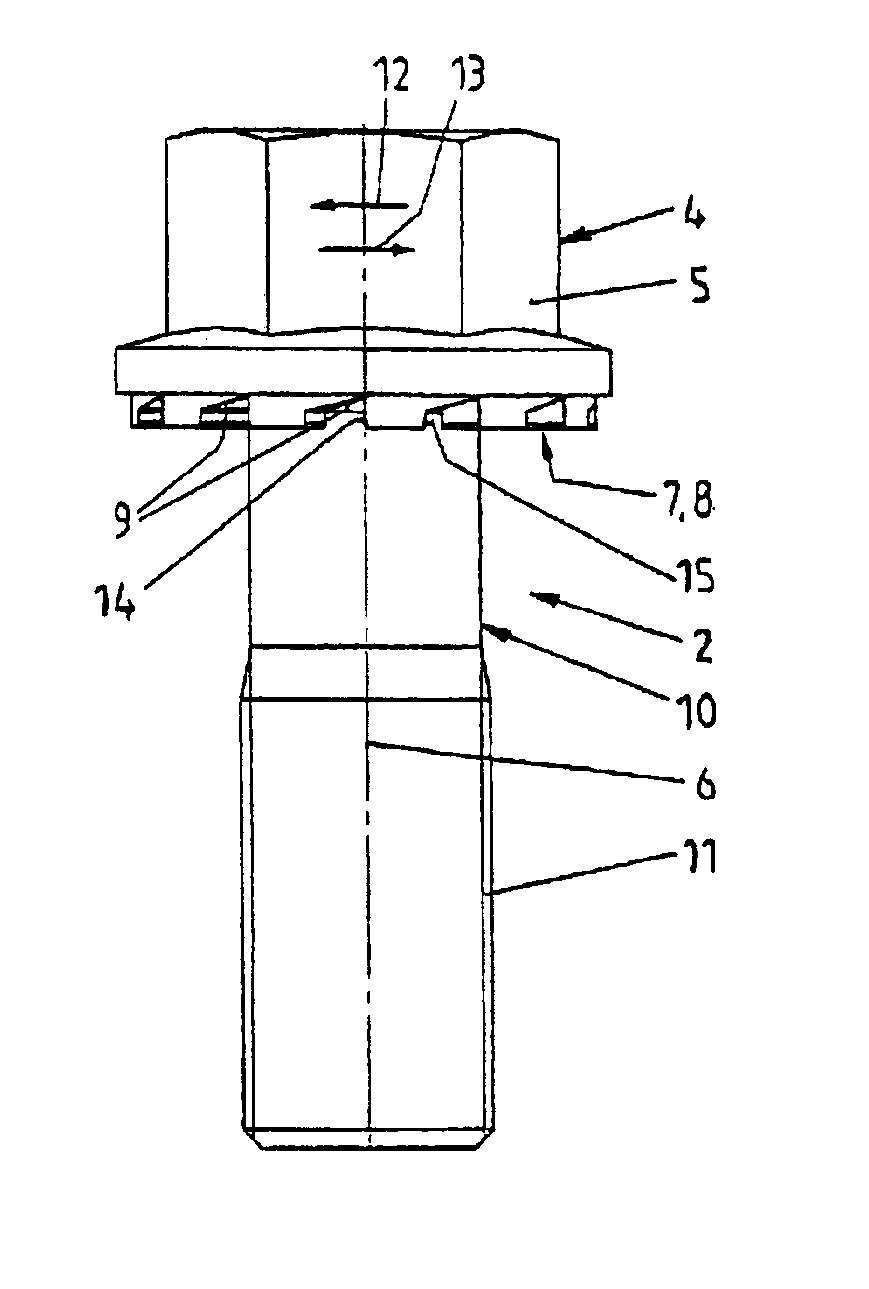
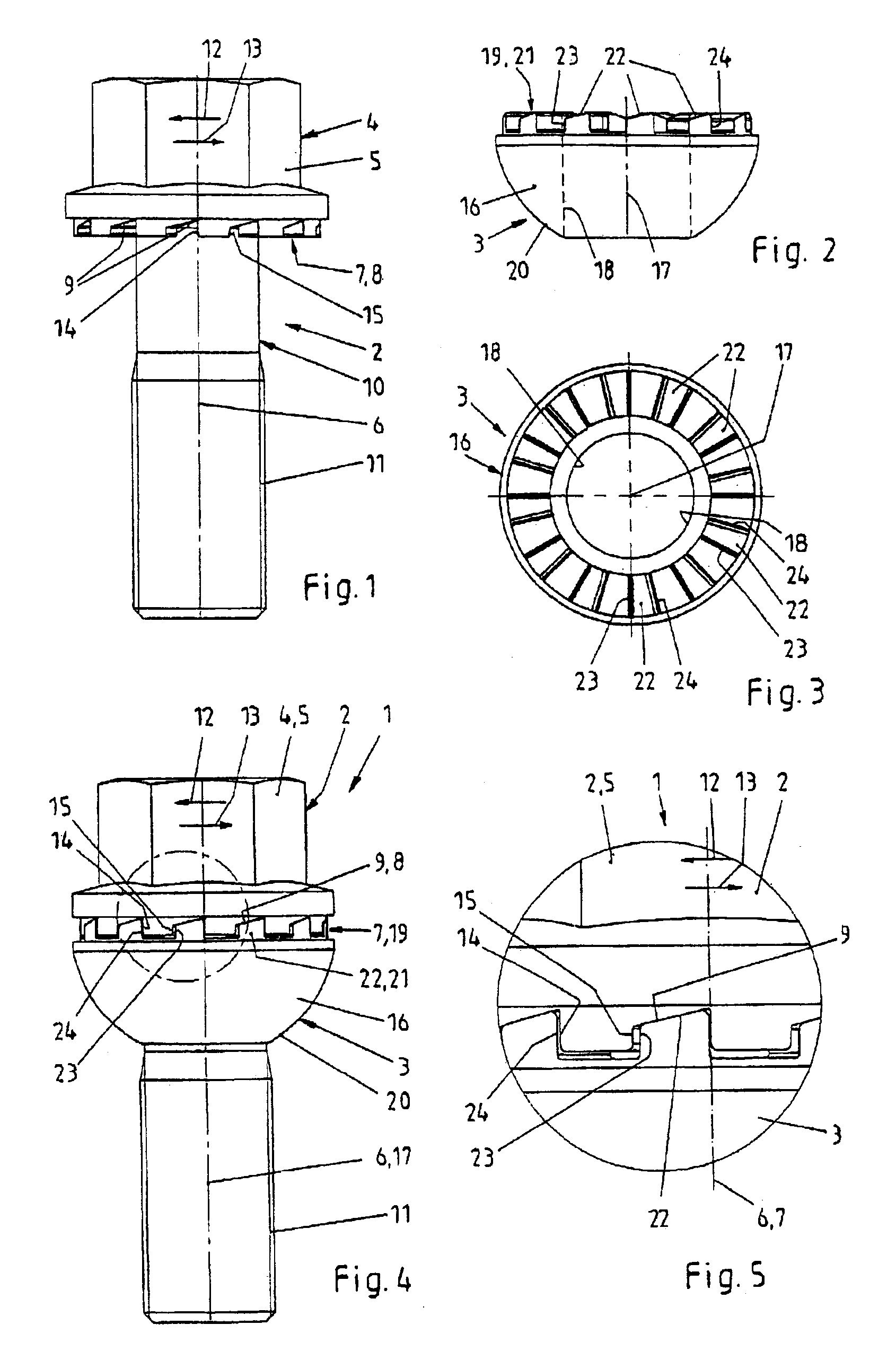
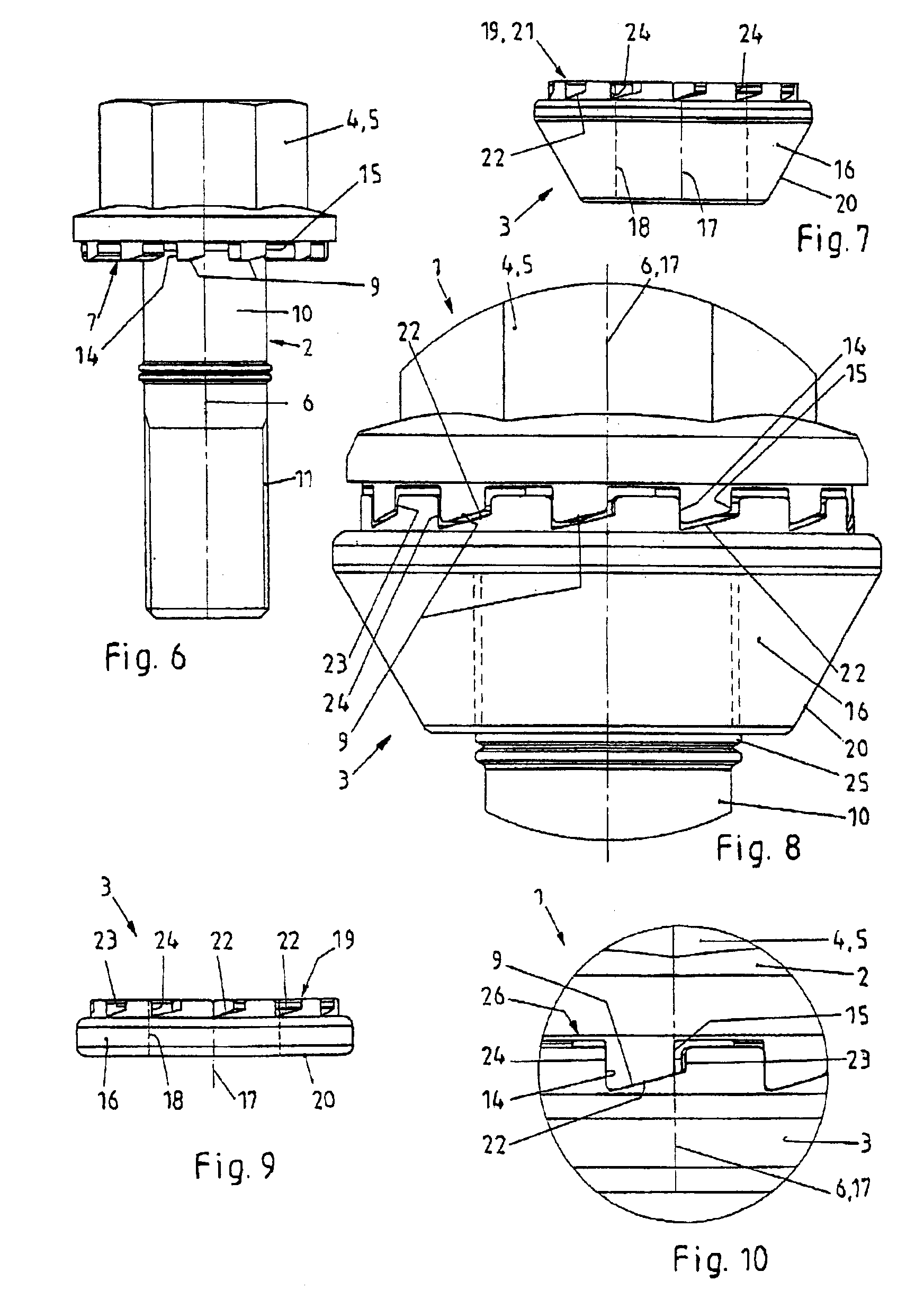
[0008]The novel fastener provides a securing effect to the screw element in the loosening direction of rotation when forces being directed in the loosening direction of rotation during loads act upon the screw element. The detachable fastener includes a low number of elements, it may be easily and securely mounted and demounted, and it may be reused.
[0009]The present invention is based on the concept to improve detachable fasteners being designed as screws or nuts and including a supporting ring without increasing the number of elements. The use of a wedge-shaped surface tooth arrangement results in an increase of the axial force during unintentional loosening of the screw. This means that the wedge-shaped surface tooth arrangements counteract undesired loosening effects of the fastener when forces act upon the fastener. For example, transverse forces acting upon the elements of the fastener under certain load conditions lead to the wedge-shaped surface tooth arrangements sliding upon one another. This sliding movement results in an increase of the axial force and in the loosening movement being stopped. Consequently, further decrease of pre-tension is counteracted. Consequently, only a strongly limited relative movement takes place. Each tendency of a relative movement is counteracted. This effect will be attained for a plurality of times even under different loading conditions. These effects are attained during unintentional self loosening or untightening effects. In this way, losses of pre-tension are compensated. This especially applies when pre-tension has already been decreased by unpreventable setting effects, and when the portion of the
transverse force to be transmitted by frictional engagement between the elements has also been decreased. Similar applies when the joint has not been tightened to the appropriate torque—for example by inappropriate
assembly or maintenance—and the level of pre-tension required for a secure joint has not been reached. In this way, the novel fastener also improves safety of joints being realized with the novel fastener.
[0010]The novel fastener includes two pairs of stop surfaces being active between the screw element and the securing ring. One of the pairs of stop surfaces is designed and arranged to transmit torque in the tightening direction of rotation, and the other pair of stop surfaces is designed and arranged to transmit torque in the loosening direction of rotation. The pairs of stop surfaces are arranged with a clearance between one another. In other words, there is an effective distance or a rotation angle distance between the pairs of stop surfaces. The clearance is used to allow for sliding of the sliding surfaces of the wedge-shaped tooth arrangements upon one another without skipping of the wedge-shaped surface tooth arrangements. Skipping is to be understood herein as the movement of a first protrusion of the first tooth arrangement from a first impression of the second tooth arrangement beyond a first protrusion of the second tooth arrangement into a second impression of the second tooth arrangement. In this way, sliding is only possible to a limited extent, the sliding path in the circumferential direction being less than the division of the wedge-shaped surface tooth arrangements. To securely prevent the described undesired skipping movement, the novel fastener includes at least one pair of stop elements being effective in the tightening direction of rotation and at least one pair of stop surfaces being effective in the untightening direction of rotation.
[0011]The arrangement of the wedge-shaped surface tooth arrangements and of the pairs of stop surfaces with respect to one another is chosen such that the pair of stop surfaces being effective in the tightening direction of rotation defines the relative position of the sliding surfaces of the wedge-shaped surface tooth arrangements in the maximum approached rotational position between the screw element and the securing ring. In this way, there is no sliding friction between the sliding surfaces of the wedge-shaped surface tooth arrangements during tightening of the fastener. The maximum
usable sliding path is defined thereby. The pair of stop surfaces being effective in the loosening direction of rotation becomes effective no earlier than when a part of the sliding path and its projection, respectively, has been exceeded.
[0014]The first and second wedge-shaped surface tooth arrangements are designed and arranged such that there will be a securing effect when forces act upon the screw element in the loosening direction of rotation. The securing effect will secure the connection between the screw element, the securing ring and the component being joint by the fastener. Unintentional, self loosening effects will be prevented under an increase of the axial force resulting in the screw element and the securing ring being rotated against each other to a limited extent. On the other hand, when the screw element is intentionally tightened or loosened the respective pair of stop surfaces will positively engage to commonly rotate the screw element and the securing ring. The limited movement in two opposite axial directions during unintentional loosening effects takes place within the projection of a sliding surface.
[0016]There is the possibility of securing the engaging position between the screw element and the securing ring by arranging the securing ring at the screw element in a captive way and in a way to be rotatable corresponding to the clearance. The
clutch element and the tooth arrangement, respectively, is always located in the engaging position. In this way, the starting position of the screw element with respect to the securing ring is determined. When tightening the fastener the sliding surfaces initially slide upon one another such that the screw element and the securing ring approach one another in an axial direction to attain the closest position. In this way, the beginning of the sliding path is determined and reached, respectively. When the sliding path being formed by the wedge-shaped surface tooth arrangements begins directly at the pair of stop surfaces being effective in the tightening direction of rotation, the sliding path is used in an optimum way. During untightening of the fastener, the sliding surfaces at the screw element and at the securing ring also slide upon one another without the danger of skipping effects. It is also possible that the shoulders form the pair of stop surfaces being effective in the tightening direction of rotation, and that contact during tightening is realized at this place. In this case, it makes sense to chose the clearance existing between the pairs of stop surfaces to be identical, too, or to be greater than the projection of the wedge-shaped surface tooth arrangements, and to arrange the pairs of stop surfaces with respect to the wedge-shaped surface tooth arrangements such that the clearance is located outside of the projection of a wedge-shaped surface. This arrangement allows for the possibility of limiting and reducing, respectively, the actual sliding path. At the same time, it is possible to accept greater tolerances at the pair of stop surfaces not actually being active in the tightening
sense of direction.


