Thermoelectric transducer

a technology of thermoelectric transducers and transducers, which is applied in the manufacture/treatment of thermoelectric devices, electrical apparatus, and thermoelectric devices with peltier/seeback effects. it can solve the problems of increasing the assembling steps of manufacturing thermoelectric transducers, difficult to accurately arrange thermoelectric devices, and difficult to effectively improve thermoelectric converting efficiency of thermoelectric transducers. achieve the effect of improving thermoelectric converting efficiency and being easy to manufactur

Inactive Publication Date: 2006-10-05
DENSO CORP
View PDF4 Cites 20 Cited by
  • Summary
  • Abstract
  • Description
  • Claims
  • Application Information

AI Technical Summary

Benefits of technology

[0008] In view of the foregoing problems, it is an object of the present invention to provide a thermoelectric transducer, which can be easily manufactured while improving thermoelectric converting efficiency.
[0009] According to an aspect of the present invention, in a thermoelectric transducer, a thermoelectric device substrate includes a plurality of P-type thermoelectric devices, a plurality of N-type thermoelectric devices, and an insulating board for holding the plurality of P-type thermoelectric devices and N-type thermoelectric devices, and the plurality of P-type thermoelectric devices and N-type thermoelectric devices are alternately arranged on the insulating board. Each of a plurality of electrode members is connected to two end portions of adjacent N-type thermoelectric device and P-type thermoelectric device for electrically connecting the adjacent N-type thermoelectric device and P-type thermoelectric device. In addition, the thermoelectric transducer includes a plurality of heat exchanging members each of which includes an electrode portion connectable to the electrode member, and a heat exchanging portion for exchanging heat transmitted from the electrode portion. In the thermoelectric transducer, the plurality of heat exchanging members are located at two sides of the thermoelectric device substrate to form a heat absorbing part and a heat radiating part partitioned from each other by the thermoelectric device substrate. In addition, the electrode portions and the heat exchanging portions have, respectively, the same shapes, in all the heat exchanging members, and the electrode portions and the heat exchanging portions are arranged in the same direction in all the heat exchanging members of each of the heat absorbing part and the heat radiating part. Accordingly, it is possible to use one type of the heat exchanging members, thereby effectively reducing manufacturing cost of the heat exchanging members.
[0010] For example, the plurality of N-type thermoelectric devices and the plurality of P-type thermoelectric devices are arranged to form plural thermoelectric device groups arranged in plural lines in an arrangement direction, and each of the plural thermoelectric device groups is constructed with a pair of the N-type thermoelectric device and the P-type thermoelectric device electrically connected to each other by the electrode member. In this case, two heat exchanging members are arranged on one electrode member that connects the N-type thermoelectric device and the P-type thermoelectric device in a direction perpendicular to the arrangement direction at an outer end of the thermoelectric device groups, and the N-type thermoelectric device and the P-type thermoelectric device in each thermoelectric device group inside of the outer end are electrically connected by one electrode member extending in a direction parallel to the arrangement direction. Furthermore, the two heat exchanging members extend in the arrangement direction at the outer end of the thermoelectric device groups. Therefore, thermoelectric converting efficiency can be effectively improved.
[0014] According to another aspect of the present invention, a thermoelectric transducer includes: a thermoelectric device substrate that has a plurality of P-type thermoelectric devices, a plurality of N-type thermoelectric devices, and an insulating board for holding the plurality of P-type thermoelectric devices and N-type thermoelectric devices alternately arranged on the insulating board; and a plurality of heat exchanging members each of which includes an electrode portion bonded to two end portions of adjacent N-type thermoelectric device and P-type thermoelectric device for electrically connecting the adjacent N-type thermoelectric device and P-type thermoelectric device, and a heat exchanging portion for exchanging heat transmitted from the electrode portion. In this thermoelectric transducer, the plurality of heat exchanging members are located at two sides of the thermoelectric device substrate to form a heat absorbing part and a heat radiating part partitioned from each other by the thermoelectric device substrate, the electrode portions and the heat exchanging portions have, respectively, the same shapes in all the heat exchanging members, and the electrode portions and the heat exchanging portions are arranged in the same direction in all the heat exchanging members in each of the heat absorbing part and the heat radiating part. Accordingly, all the heat exchanging member can be formed into one type, and the thermoelectric transducer can be easily formed.

Problems solved by technology

Accordingly, it is difficult to accurately arrange the thermoelectric devices each having a small size and the electrode members, thereby assembling steps for manufacturing the thermoelectric transducer are increased.
Furthermore, when the heat exchanging members are simply arranged at connection portions between adjacent thermoelectric devices in accordance with the arrangement of the thermoelectric devices, it is difficult to effectively improve thermoelectric converting efficiency in the thermoelectric transducer.

Method used


Image

  • Thermoelectric transducer
  • Thermoelectric transducer
  • Thermoelectric transducer

Examples


second embodiment

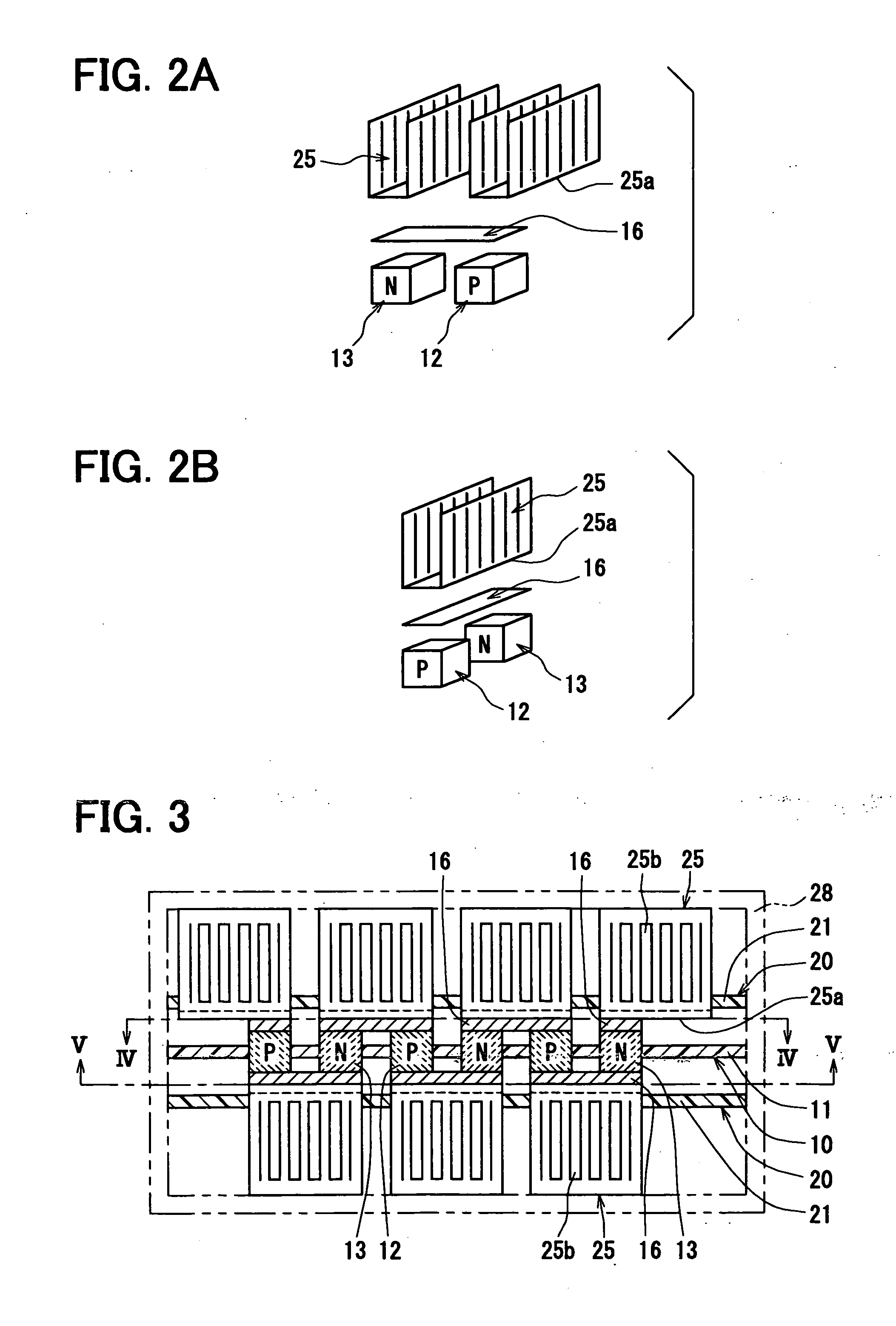
[0060] In the above-described first embodiment, each electrode member 16 arranged on the adjacent thermoelectric devices 12, 13 at the outer end of the thermoelectric device groups is formed into the same shape as that of the electrode member 16 arranged on the adjacent thermoelectric devices 12, 13 positioned inside of the outer end of the thermoelectric device groups, as shown in FIGS. 2A and 2B. Therefore, the electrode member 16 arranged on the adjacent thermoelectric devices 12, 13 at the outer end of the thermoelectric device groups extend in a direction perpendicular to the flow direction of air, and a part of each of the two heat exchanging members 25 is bonded to the electrode member 16. In contrast, in the second embodiment, the surface area of the electrode member 16 arranged on the adjacent thermoelectric devices 12, 13 at the outer end of the thermoelectric device groups is enlarged.

[0061] For example, as shown in FIG. 8A and 8B, the electrode member 16 arranged on the...

third embodiment

[0063] In the above-described first and second embodiments, the heat exchanging member 25 is bonded to the adjacent thermoelectric devices 12, 13 through the electrode member 16, while all the heat exchanging members 25 are formed into the same shape. In contrast, in the third embodiment, the electrode portions 25a of the heat exchanger members 25 are directly bonded to the thermoelectric devices 12, 13, while all the heat exchanging members 25 are formed into the same shape.

[0064] For example, as shown in FIGS. 9 and 10, an electrode member 16a is located to the first insulating board 11, so as to electrically connect with each other the electrode portions 25a of the two heat exchanging members 25 at the outer end of the thermoelectric groups. In this case, the electrode portions 25a of the two heat exchanging members 25 at the outer end of the thermoelectric groups can be electrically connected with each other through the electrode member 16a. The electrode member 16a can be form...


PUM


Abstract

In a thermoelectric transducer, a plurality of P-type thermoelectric devices and N-type thermoelectric devices are alternately arranged on an insulating board, and each of a plurality of electrode members is connected to two end portions of adjacent N-type and P-type thermoelectric devices for electrically connecting the adjacent N-type and P-type thermoelectric devices. Furthermore, a plurality of heat exchanging members each of which includes an electrode portion connectable to the electrode member and a heat exchanging portion for exchanging heat transmitted from the electrode portion are located at two sides of a thermoelectric device substrate to form a heat absorbing part and a heat radiating part partitioned from each other. The electrode portions and the heat exchanging portions have, respectively, the same shapes, and the electrode portions and the heat exchanging portions are arranged in the same direction in all the heat exchanging members of each heat absorbing or radiating part.

Description

CROSS REFERENCE TO RELATED APPLICATION [0001] This application is based on Japanese Patent Application No. 2005-109053 filed on Apr. 5, 2005, the contents of which are incorporated herein by reference in its entirety. BACKGROUND OF THE INVENTION [0002] 1. Field of the Invention [0003] The present invention relates to a thermoelectric transducer that has a series circuit including N-type thermoelectric devices and P-type thermoelectric devices and absorbs or radiates heat when a DC current is passed through the series circuit. More particularly, present invention relates to the shape of heat exchanging members located at connection portions between adjacent thermoelectric devices. [0004] 2. Description of the Related Art [0005] As one of conventional thermoelectric transducers, there is proposed a thermoelectric transducer that has N-type thermoelectric devices and P-type thermoelectric devices alternately arranged in the shape of a plane. In this thermoelectric transducer, the respe...

Claims


Application Information

Patent Timeline
Patent Type & Authority Applications(United States)
IPC IPC(8): H01L35/34H01L35/28
CPCH01L35/32H01L35/30H10N10/13H10N10/17
Inventor KUROYANAGI, ISAOMATSUOKA, AKIONIIMI, YASUHIKOYAMAMOTO, TAKASHIHATANO, YUKINORIMARUO, SHIZUONAKAMURA, FUMIAKI
Owner DENSO CORP
Why Eureka
Try Eureka