Relief valve for a grease gun

a grease gun and relief valve technology, applied in the direction of conduits/junctions, lubrication elements, manual lubrication, etc., can solve the problems of inconvenient use, non-disclosure of patent structure, polluting the environment, etc., and achieve the effect of convenient broadening the application of patents

Inactive Publication Date: 2006-10-05
TUNG TIEN CHEN
View PDF10 Cites 15 Cited by
  • Summary
  • Abstract
  • Description
  • Claims
  • Application Information

AI Technical Summary

Benefits of technology

[0007] An object of the present invention is to provide a relief valve for a grease gun with which the relief pressure can be adjusted based on need.
[0008] Another object of the present invention is to provide a relief valve with which the relief pressure can be adjusted conveniently for broadening the application thereof.

Problems solved by technology

However, the preceding US patents do not disclose structure with regard to grease being moving back the grease barrel.
It is known that it is wasteful to discharge the grease outside the grease gun with the relief device and it pollutes the environment and makes dirty to the user if the discharged grease is left outside.
As a result, it is inconvenient while in use.

Method used


Image

  • Relief valve for a grease gun
  • Relief valve for a grease gun
  • Relief valve for a grease gun

Examples


Embodiment Construction

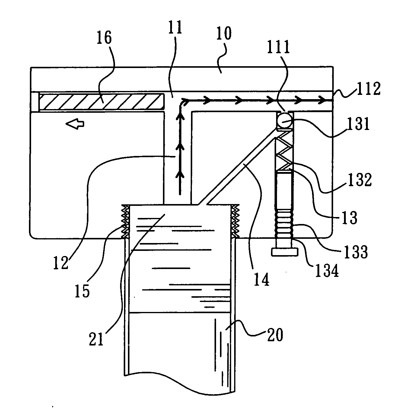
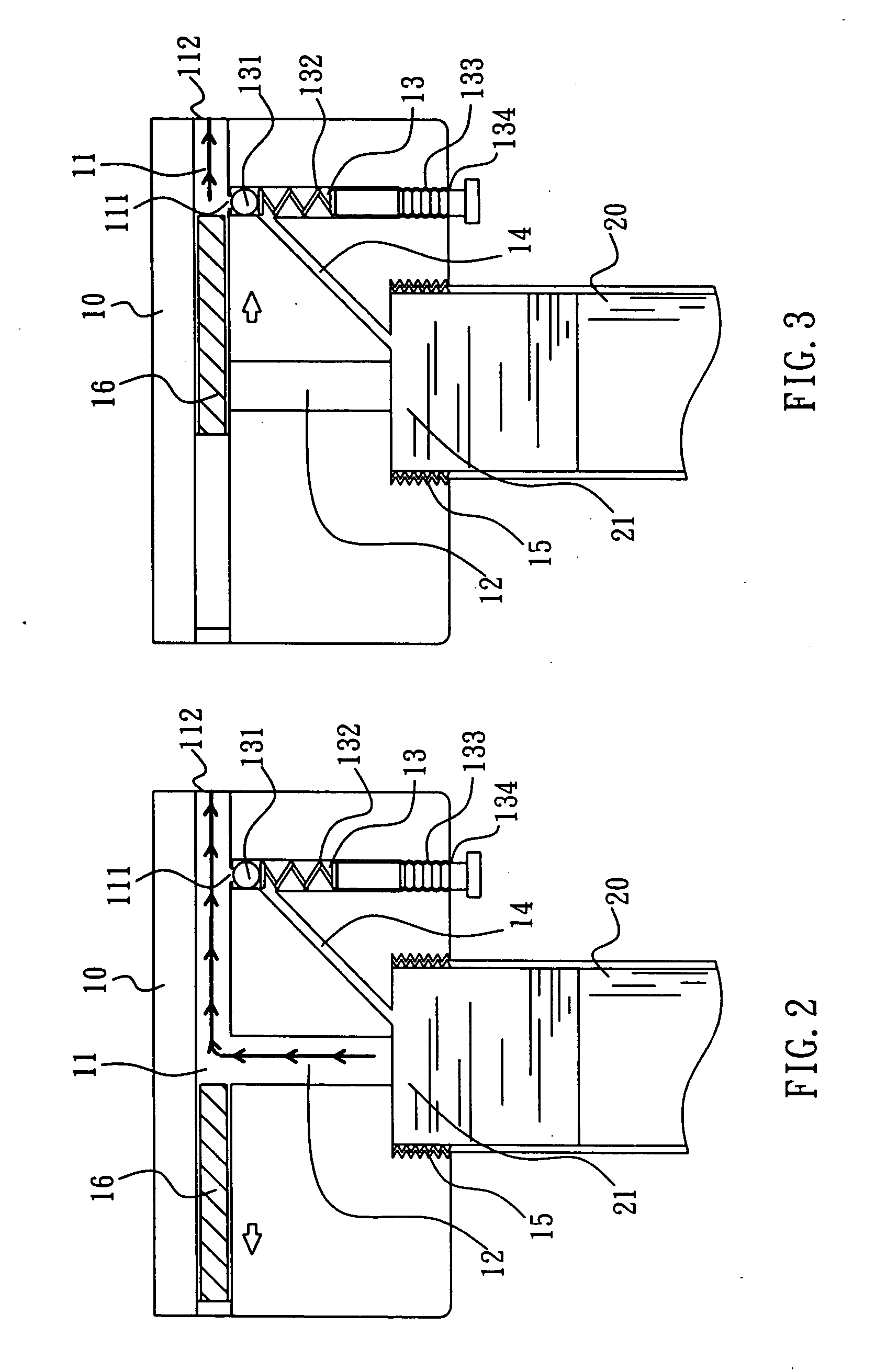
[0015] Referring to FIGS. 2, 3 and 5, a relief valve for a grease gun according to the present invention includes a main member 10 with a compression passage 11, a first passage 12, a second passage 13, a third passage 14 and an opening 15 associated with a grease barrel 20. The compression passage 11 has a relief outlet 111 and an external opening 112 communicating with the main member 10. A plunger 16 is received in the compression passage 11. The relief outlet 111 is disposed near the external opening 112. The first passage 12 communicates with the compression passage 11 and the opening 15 at both ends thereof respectively. The second passage 13 has a relief outlet 111 at an end thereof to communicate with the compression passage 11 and has an external opening 134 at another end thereof at the bottom of the main member 10. The second passage 13 receives a ball 131 and an elastic element 132 and engages with a screw rod 133. The screw rod 133 has a head end extends outward the ext...


PUM


Abstract

A grease gun includes a relief valve and a grease barrel. The relief valve has a main member associated with the grease barrel. The main member further includes a compression passage with a relief outlet and a first opening, a first passage communicating the with compression passage at one end thereof and being joined to the barrel opening with the another end thereof, a second passage communicating with the relief outlet at one end thereof and having a second opening communicating with outside of the main member for receiving a ball, an elastic element and a screw rod and a third passage communicating with the second passage at one end thereof and joining the barrel opening at another end thereof. Once the screw rod is adjusted the length thereof in the second passage for regulating compression amount of the elastic element, the force of the ball for blocking the relief outlet is capable of being controlled.

Description

BACKGROUND OF THE INVENTION [0001] 1. Field of the Invention [0002] The present invention is related to a grease gun for the grease being injected into a machine or apparatus and particularly to a relief valve for an electric or pneumatic grease gun. [0003] 2. Brief Description of Related Art [0004] Patents such as U.S. Pat. No. 5,779,05, U.S. Pat. No. 4,219,131 and U.S. Pat. No. 4,063,618, U.S. Pat. No. 4,062,425 disclose a grease gun with a relief device. However, the preceding US patents do not disclose structure with regard to grease being moving back the grease barrel. It is known that it is wasteful to discharge the grease outside the grease gun with the relief device and it pollutes the environment and makes dirty to the user if the discharged grease is left outside. [0005] Referring to FIG. 1, Issue No. 242941 of Taiwanese Patent Official Gazette discloses an electric grease gun, which provides a feature that an automatic relief outlet 32 is located near the outer opening of...

Claims


Application Information

Patent Timeline
Patent Type & Authority Applications(United States)
IPC IPC(8): F16N21/00F16N3/12
CPCF16N3/12
Inventor TUNG, TIEN-CHEN
Owner TUNG TIEN CHEN
Why Eureka
Try Eureka