Automatic purging and easy dispensing aerosol valve system

a valve system and automatic technology, applied in the direction of liquid dispensing, liquid transfer devices, packaging, etc., can solve the problems of significant propellant loss, low sealing efficiency, and inability to use mechanical break-up inserts in the nozzle, and achieve the effect of easy opening

Active Publication Date: 2006-10-05
PRECISION VALVE CORP
View PDF15 Cites 28 Cited by
  • Summary
  • Abstract
  • Description
  • Claims
  • Application Information

AI Technical Summary

Benefits of technology

[0006] The present invention is intended to provide a self-purging aerosol valve system that is also easy to open and characterized by the absence of any return spring acting directly upon the valve stem. The present invention is for use with a container holding a product to e dispensed and a propellant gas. The present invention comprises a mounting cup, a valve housing captured by the mounting cup, a valve stem extending within and above said valve housing, a valve stem sealing gasket which cooperates with the stem to comprise a first valve of the aerosol valve system, a valve housing extension, and a check valve element and biasing element positioned within the valve housing extension and comprising a second valve of the aerosol valve system. The biasing element may be a spring or a flexible membrane with blockable openings, for example. The valve housing has a first opening, and a second opening for entry of propellant gas from the container into the valve housing. The check valve element, for example a check ball or a portion of a flexible membrane, and said first opening in the valve housing comprise a second valve of the valve system. The valve stem has an internal channel for product dispensing, one or more orifices extending through the side wall of the stem for product and gas entry into the stem internal channel, and an annular groove in the stem side wall within which the stem gasket seats and seals said one or more orifices when the aerosol valve stem is not actuated. The valve housing extension has an opening therein for product in the container to enter. The biasing element in the valve housing extension biases the check valve element in the valve housing extension against the valve housing first opening when the aerosol valve is not actuated; said aerosol valve stem when actuated first unsealing said one or more stem orifices and only thereafter unseating the check valve element by action of the stem against the check valve element to allow product to enter the valve housing extension, valve housing, the one or more stem orifices and the stem internal channel. The aerosol valve system, when actuation ceases, results in the biased check valve element pushing the stem upwardly and closing the said second valve to product flow, followed thereafter, before the first valve is closed, by stem separation from the check valve element and propellant gas flow through the housing said second opening and through the stem one or more orifices and internal channel to purge remaining product in the housing, stem and actuator until said first valve is closed. The aerosol valve is further characterized by the absence of any return spring acting directly upon the valve stem to fully close the first valve or resist initially opening the first valve. The closing of the first valve is initiated by the check valve element biasing the valve stem upward followed, after separation of the check valve element and stem, by the gasket acting against the stem groove to assist in full closure of the first valve.

Problems solved by technology

Certain products dispensed by aerosol valves have a high solid and / or resin content formulation susceptible to clogging the aerosol valve and actuator after use, for example paint and certain hairsprays and antiperspirants.
In the process, significant propellant loss occurs.
In addition, traditional paint valve systems do not lend themselves to the use of mechanical break-up inserts in the nozzle, such inserts having small channels which easily clog.
However, such systems are expensive, involve multiple springs, require excessive force to open, do not function adequately, and / or are difficult to manufacture or assemble.
The spring has a significant upward force, thus requiring a significant downward force by the user to open and maintain the aerosol open.
The metal return spring also provides well-known corrosion problems with certain products, adds significant cost to the aerosol valve assembly, and requires a separate assembly operation.
Plastic return springs have been suggested as an alternative, but can be difficult and expensive to mold, require a significant user force to open and maintain open, and are more subject to failure than metal return springs.
Most such attempts have been inadequate and / or overly complicated in concept and construction.
One successful attempt is shown in U.S. Pat. No. 6,588,628 (Abplanalp, Bayer, Flynn) but it, as well as the other various attempts, do not provide or suggest a means for automatic purging of the valve of paint and other high solid / resin content products as discussed above.

Method used


Image

  • Automatic purging and easy dispensing aerosol valve system
  • Automatic purging and easy dispensing aerosol valve system
  • Automatic purging and easy dispensing aerosol valve system

Examples


Embodiment Construction

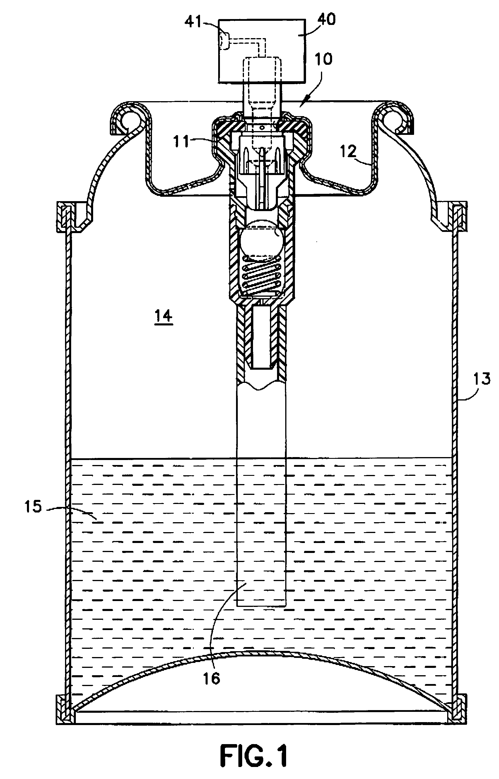
[0014] Referring to FIG. 1 an aerosol valve system or assembly designated generally as 10 is fitted and crimped into the pedestal portion 11 of a metal mounting cup closure 12 for a pressurized aerosol container 13. Container 13 is a single compartment containing both propellant 14 and one of the aforementioned products 15 to be dispensed. When the aerosol valve assembly is fully open, propellant 14 will force product 15 up through the conventional dip tube 16 and valve assembly 10 to be dispensed to the outside environment, propellant 14 also entering the valve assembly and mixing with the product, all in a manner as described hereinafter.

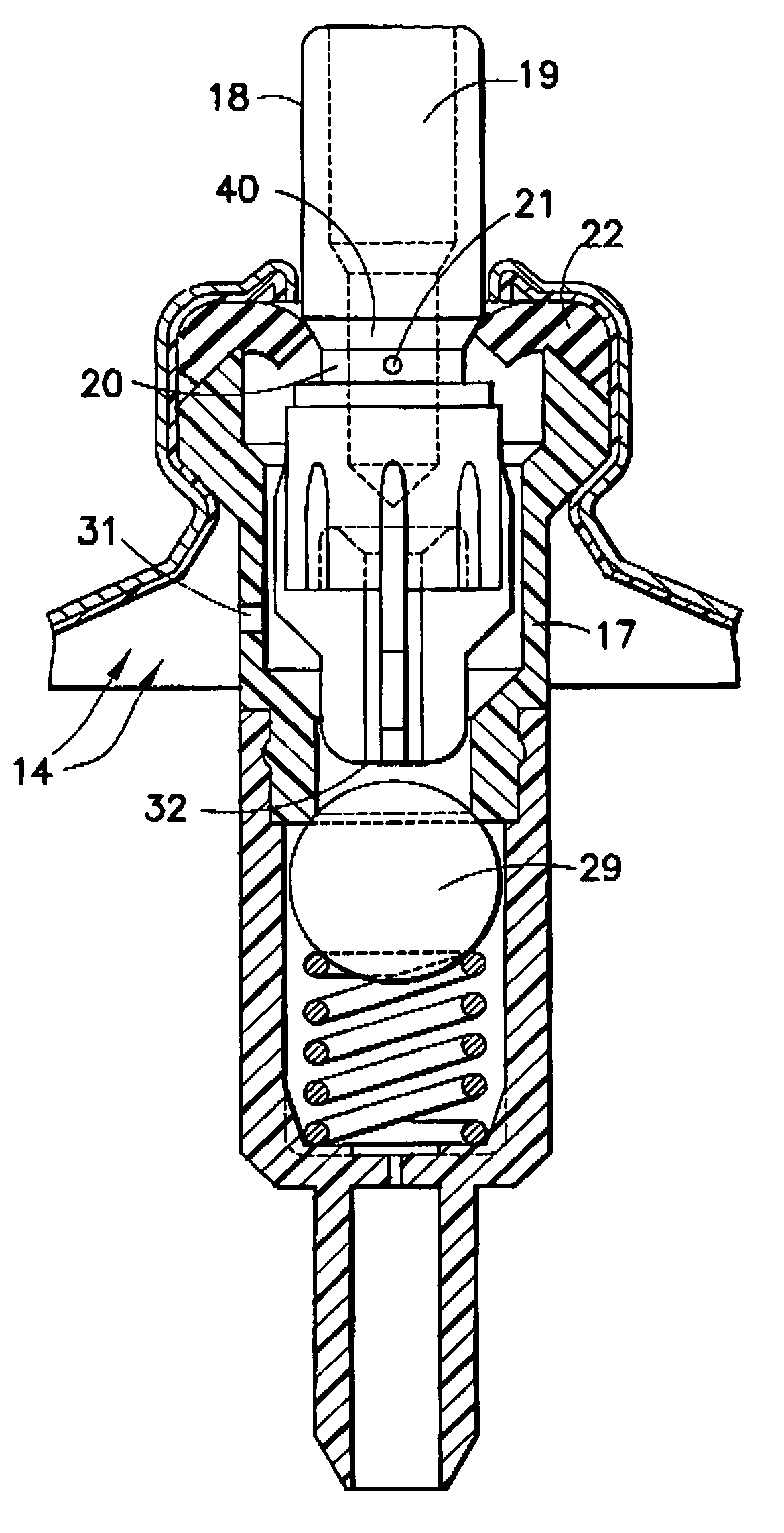
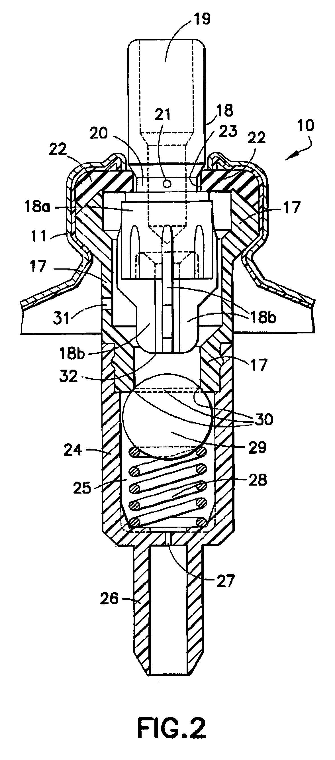
[0015]FIG. 2 illustrates the aerosol valve system 10 in a closed position. Valve housing 17 is captured at the pedestal 11 of the mounting cup in conventional fashion. Valve stem 18 extends both within and above valve housing 17. Valve stem 18 includes internal channel 19 for product dispensing, annular groove 20 in its side wall, and one or more...


PUM


Abstract

Self-purging, low force opening, aerosol valve system with an orificed valve stem groove and gasket forming a first valve for product and propellant, or propellant, flow. A check valve element, biasing element and housing first opening form a second valve for product flow. Actuating the valve stem sequentially opens first valve and then second valve. After actuation, second valve closes before first valve, and propellant from housing second opening purges valve stem and actuator until first valve closes. No first valve closing return spring acts directly on valve stem, allowing easy opening. Gasket in stem groove and product and propellant flow fully close first valve after second valve closes. High solid and/or resin content products can be dispensed through an actuator with mechanical break-up insert.

Description

FIELD OF THE INVENTION [0001] The present invention relates to aerosol valve systems to dispense products from pressurized aerosol containers and, more particularly, relates to an easy-to-open valve assembly that automatically purges product in the valve stem during full closure of the valve assembly. BACKGROUND OF THE INVENTION [0002] Certain products dispensed by aerosol valves have a high solid and / or resin content formulation susceptible to clogging the aerosol valve and actuator after use, for example paint and certain hairsprays and antiperspirants. It is well known that the users of paint in aerosol containers are instructed to invert the container after use and operate the valve actuator until a clear spray of propellant issues the nozzle, thus indicating that substantial paint residue does not remain in the valve and actuator to clog and render inoperable the sprayer. In the process, significant propellant loss occurs. In addition, traditional paint valve systems do not len...

Claims


Application Information

Patent Timeline
Patent Type & Authority Applications(United States)
IPC IPC(8): B65D83/00B67D7/06
CPCB65D83/34B65D83/48B65D83/00B65D83/44
Inventor BAYER, CHRISTIAN
Owner PRECISION VALVE CORP
Why Eureka
Try Eureka