Conductive ball mounting method, and apparatus therefor

a technology of conductive ball and mounting method, which is applied in the direction of soldering apparatus, manufacturing tools,auxillary welding devices, etc., can solve the problems of not providing a method for wiping off flux adhered, and achieve the effect of preventing the occurrence, preserving the safe run, and reliably removing the flux adhered

Active Publication Date: 2006-10-05
SHIBUYA IND CO LTD
View PDF6 Cites 9 Cited by
  • Summary
  • Abstract
  • Description
  • Claims
  • Application Information

AI Technical Summary

Benefits of technology

[0029] According to the sixth aspect of the invention, the flux removing means includes the cleaning member for wiping off the flux and moving means, and the cleaning member can be moved by the moving means to the acting position where the cleaning member contacts with the holding face and to the saved position where the contact is avoided. Therefore, the danger that the holder head collides with the flux removing means when the holder head moves near the flux removing means with a view other than that of removing the flux can be avoided to retain the safe run.
[0030] According to the seven aspect of the invention, the flux removing means is comprised for removing the flux adhered to the holding face, and has the abutting face, against which the holding face of the holder head comes into abutment, so that the holding face and the abutting face may be moved relative to each other while contacting with each other. Therefore, it is possible to reliably remove the flux adhered to the holding face, to prevent the occurrence of an excess ball, to prevent the occurrence of the residual balls, and to prevent the balls from sticking to each other at the ball feeding unit.
[0031] According to the eighth aspect of the invention, the relative movements of the abutting face and the holding face are transverse reciprocations. As a result, it is easy to control the flux removing means for removing the flux.
[0032] According to the ninth aspect of the invention, the absorptive sheet is comprised for absorbing the flux to the abutting face thereby to wipe off the flux. Therefore, the absorptive sheet can be sopped with the flux by the contact thereby to remove the flux adhered to the holder head, more reliably.
[0033] According to the tenth aspect of the invention, the shift preventing means is disposed on the abutting face for preventing the absorptive sheet from coming out of position. Therefore, the absorbent sheet can be firmly fixed at the time of the relative movements thereby to remove the flux more reliably.
[0034] According to the eleventh aspect of the invention, the holding face is formed into the mirror surface or the water-repellent surface. The flux can be removed easily and reliably.

Problems solved by technology

Still the worse, the dust adhered to the flux may be moved to bring the flux to the holding face of the holder head.
However, the related art has failed to provide a method for wiping off the flux adhered to the solder ball holding head, and an apparatus therefor.

Method used


Image

  • Conductive ball mounting method, and apparatus therefor
  • Conductive ball mounting method, and apparatus therefor
  • Conductive ball mounting method, and apparatus therefor

Examples


first embodiment

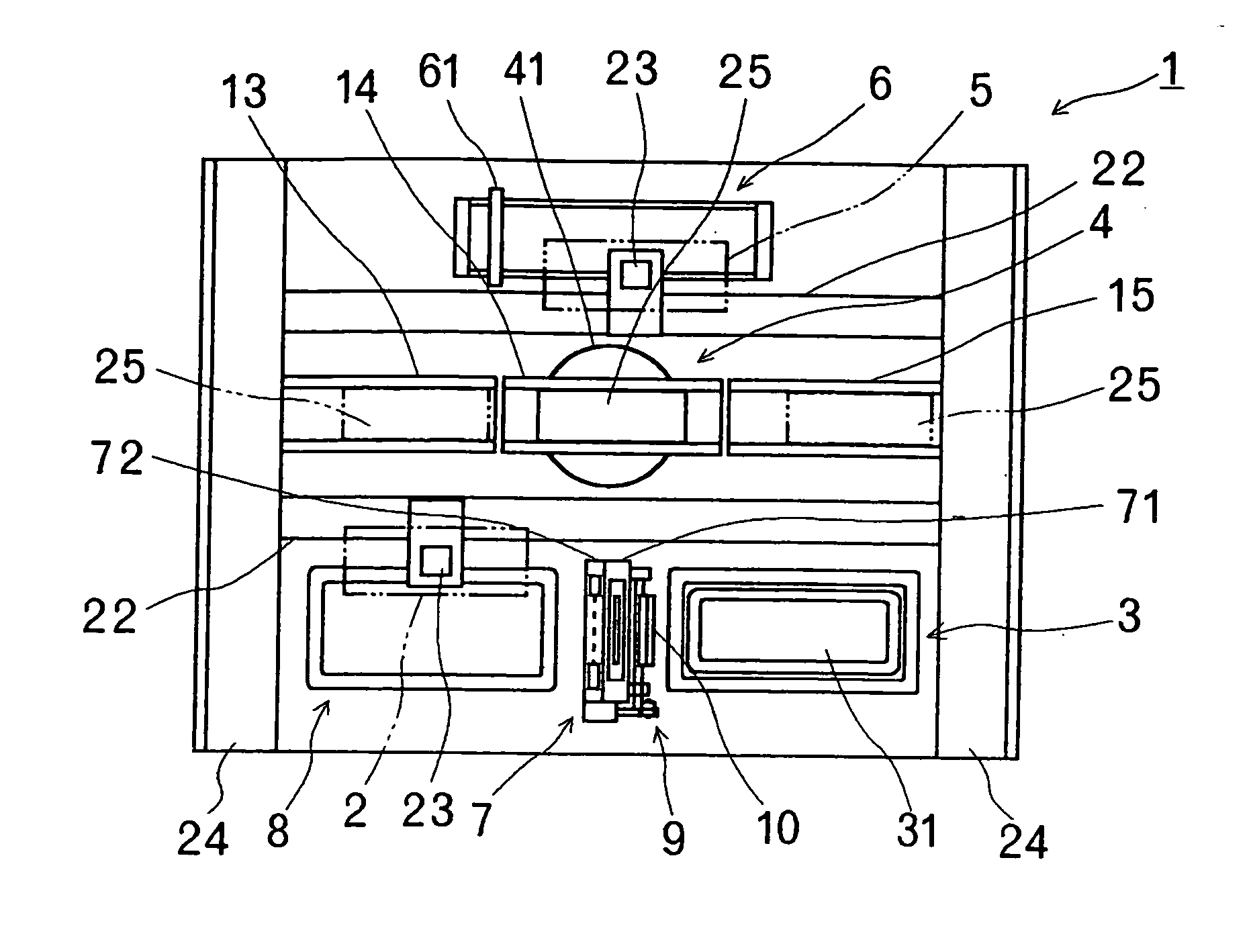
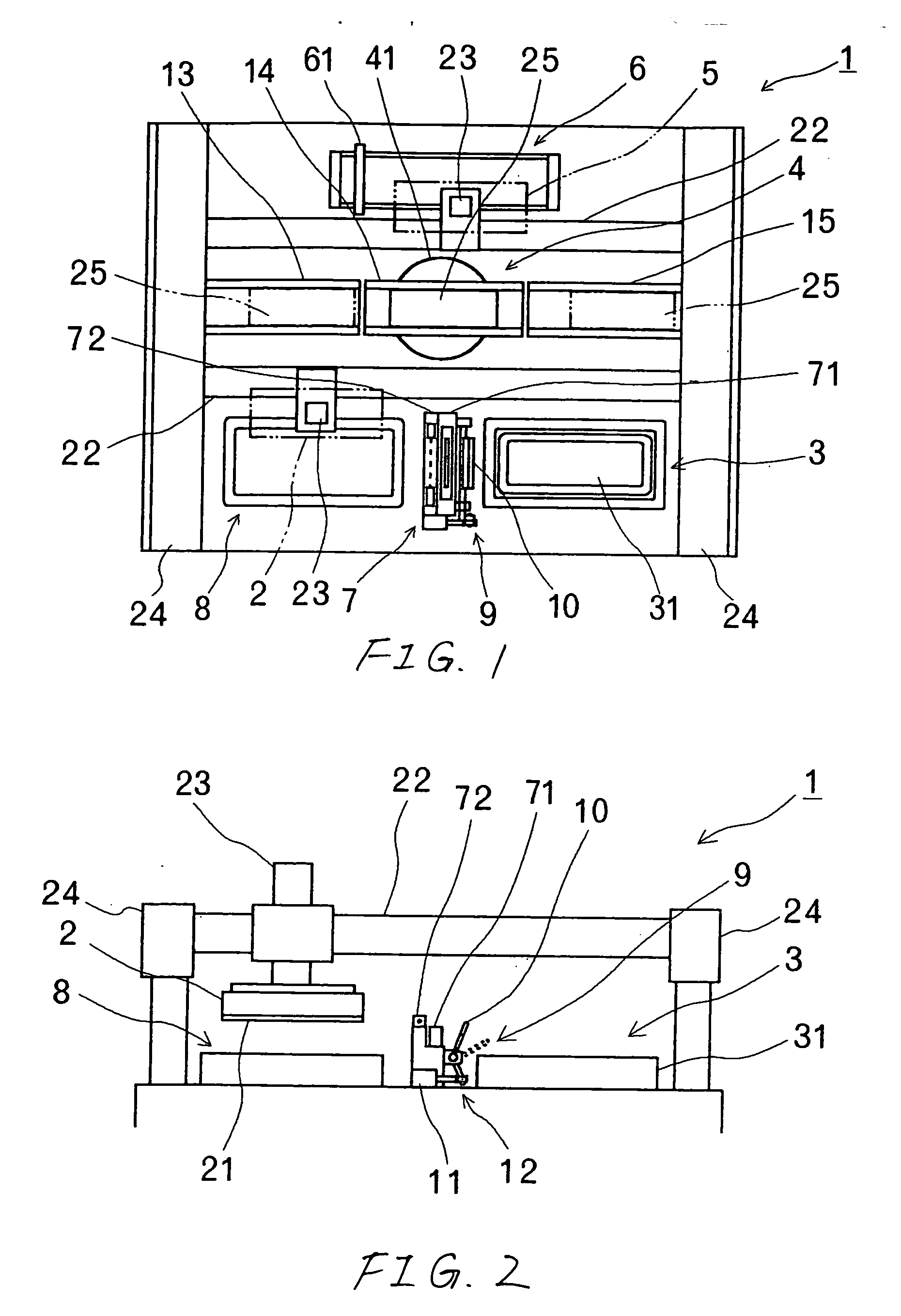
[0043] A first embodiment of the invention is described with reference to the accompanying drawings. The first embodiment uses a solder ball mounting apparatus as the conductive ball mounting apparatus. FIG. 1 is a schematically explanatory top plan view showing the entirety of a solder ball mounting apparatus 1, and FIG. 2 is a front elevation of the same.

[0044] The solder ball mounting apparatus 1 is constituted to include: a holder head 2 for sucking and holding a solder ball 30 by vacuum; a ball feeding unit 3 for reserving the solder balls 30 in multiplicity; a workpiece supporting unit 4 for supporting a substrate 25 or a workpiece to mount the solder ball 30; a transfer head 5 for transferring a flux to the substrate 25; a flux feeding unit 6 for feeding the flux to the transfer head 5; a ball inspection unit 7 acting as ball inspecting means for inspecting the ball held on a holding face 21 of the holder head 2; a solder ball recovery unit 8 for recovering the residual sold...

second embodiment

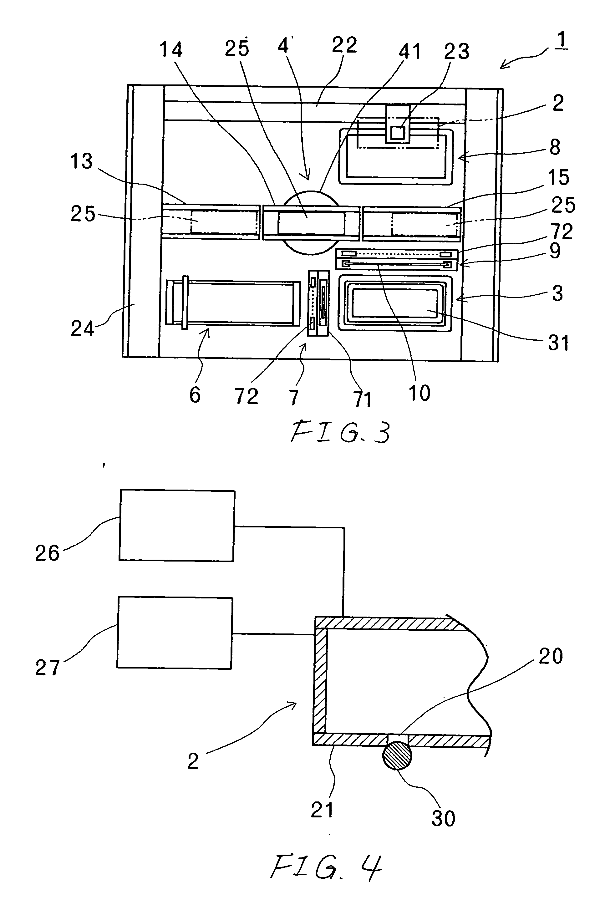
[0057] Here, the first embodiment is constituted such that the flux is transferred before the mounting action to the substrate 25 by the transfer head 5. As a second embodiment, however, there can be conceived a constitution, in which the holder head 2 moves, after it held the solder ball 30, to the flux feeding unit 6 to adhere the flux to the solder ball 30 and then to mount the ball on the substrate 25, as shown in FIG. 3. In the case of this constitution, the moving route of the holder head 2 is different from that of the first embodiment. As shown in FIG. 3, therefore, the flux feeding unit 6 is positioned in the X-axis direction (as located on the left side of FIG. 3) of the ball feeding unit 3, and the solder ball recovery unit 8 is positioned in the Y-axis direction (as located on the upper side of FIG. 3) of the ball feeding unit 3.

[0058] In either event, the ball inspection unit 7 and the flux removing unit 9 exist midway of the action route of the holder head 2 between t...

third embodiment

[0059] As a third embodiment, there can also be conceived a constitution, in which the flux removing unit 9 has a face to abut against the holding face 21 of the holder head 2 so that the flux may be removed by moving the holding face 21 and the abutting face relative to each other while the two faces contacting with each other.

[0060] The third embodiment of the invention is described with reference to the accompanying drawings. Like the first embodiment, the third embodiment uses the solder ball mounting apparatus as the conductive ball mounting apparatus. FIG. 5 is a schematically explanatory top plan view showing the entirety of the solder ball mounting apparatus 1 of the third embodiment, and FIG. 6 is a front elevation of the same. Here, the description of the components common to the first embodiment is omitted by designating them by the same reference numerals.

[0061] The holding face 21 of the holder head 2 is finished into a mirror surface so that it can wipe off the adher...


PUM

PropertyMeasurementUnit
diameteraaaaaaaaaa
conductiveaaaaaaaaaa
pressureaaaaaaaaaa

Abstract

A conductive ball mounting apparatus and method for holding a conductive ball on the holding face, as has a suction port formed therein, of a holder head thereby to mount the held conductive ball, while interposing a flux therein, on a workpiece. After the end of the mounting action and before a next conductive ball is held, flux removing means for removing the flux adhered to the holding face is brought into abutment against the holding face of the holder head thereby to remove the flux from holding face.

Description

[0001] This application is based on Japanese Patent Applications No. 2005-101360 and 2005-251092, which are incorporated herein by reference. BACKGROUND OF THE INVENTION [0002] 1. Field of the Invention [0003] The present invention relates to improvements in a conductive ball mounting method and an apparatus therefor. The conductive ball mounting method and apparatus have been developed with a main view to removing the flux which is adhered to the holding face, as has a suction port formed therein, of a holder head. [0004] 2. Description of the Related Art [0005] In case the conductive ball such as a solder ball is to be mounted in an electrode on a workpiece such as a substrate, there has been usually adopted a mounting method for adhering an adhesive flux to the solder ball or the electrode. [0006] The space at the solder ball mounting time between the substrate and the holder head of the solder ball is so extremely short as is exemplified by one half to three quarters of the sold...

Claims


Application Information

Patent Timeline
Patent Type & Authority Applications(United States)
IPC IPC(8): B23K1/00B23K1/08B23K31/02
CPCB23K1/206H05K3/3478B23K3/0623
Inventor KAJII, YOSHIHISA
Owner SHIBUYA IND CO LTD
Why Eureka
Try Eureka