Eureka AIR delivers breakthrough ideas for toughest innovation challenges, trusted by R&D personnel around the world.

Method and system for multi-frequency inductive ratio measurement

a multi-frequency inductive ratio and measurement method technology, applied in the direction of resistance/reactance/impedence, line-transmission details, instruments, etc., can solve the problems of false gap and/or vibration output of the system, change in the resistance and/or reactance of the transducer and/or cable,

Inactive Publication Date: 2006-10-05
BAKER HUGHES HLDG LLC
View PDF14 Cites 7 Cited by
  • Summary
  • Abstract
  • Description
  • Claims
  • Application Information

AI Technical Summary

Problems solved by technology

Because the indicated gap between the transducer and the target is based upon the parallel impedance as sensed by the conditioning circuitry, any change that modifies the impedance of the transducer and / or cable as sensed by the conditioning circuitry may cause a false gap and / or vibration output from the system.
A fluid leaking into the cable or transducer may cause a change in the resistance and / or reactance of the transducer and / or cable.
However, it may be impracticable due to machine operational commitments or the cable being located in a relatively extreme environment.

Method used


Image

  • Method and system for multi-frequency inductive ratio measurement
  • Method and system for multi-frequency inductive ratio measurement
  • Method and system for multi-frequency inductive ratio measurement

Examples


Embodiment Construction

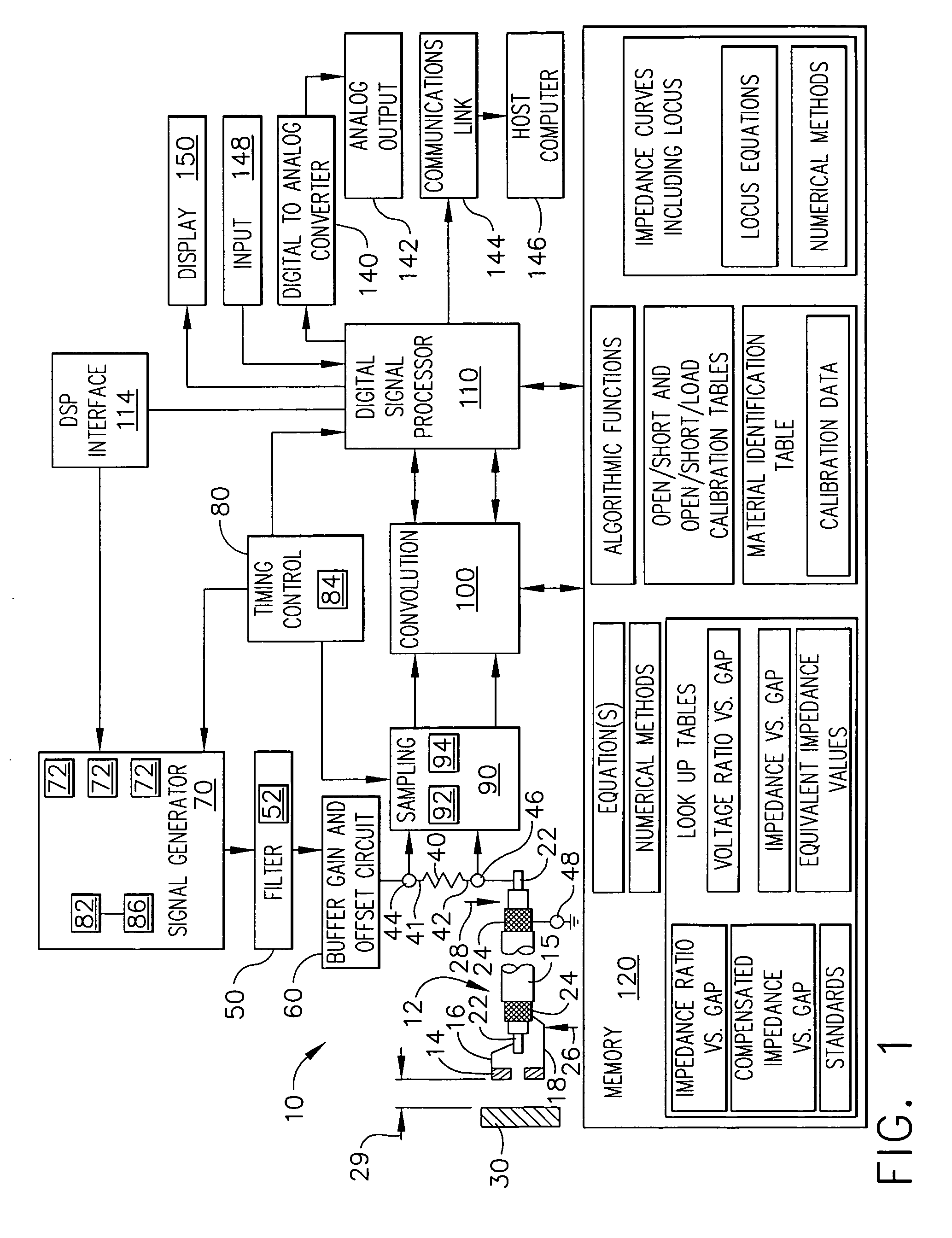
[0010]FIG. 1 is a schematic block diagram of an exemplary digital eddy current system 10 that includes a transducer 12 operatively coupled to system 10. System 10 includes a voltage ratio method (VR method) used for digitally measuring an unknown electrical impedance of transducer 12. Transducer 12 includes an integral sensing element or coil 14 and a multi-conductor transducer cable 15. Sensing element 14 includes a first electrical lead 16 and a second electrical lead 18. Transducer cable 15 includes a first conductor 22 and a second conductor 24 extending from a first end 26 to a second end 28 of transducer cable 15.

[0011] At cable first end 26, first conductor 22 and second conductor 24 are each operatively coupled to the first electrical lead 16 and second electrical lead 18 of sensing element 14, respectively. At cable second end 28, first conductor 22 is coupled to second terminal 42 of resistor 40 at node 46 and second conductor 24 is coupled to ground node 48, thereby grou...


PUM


Abstract

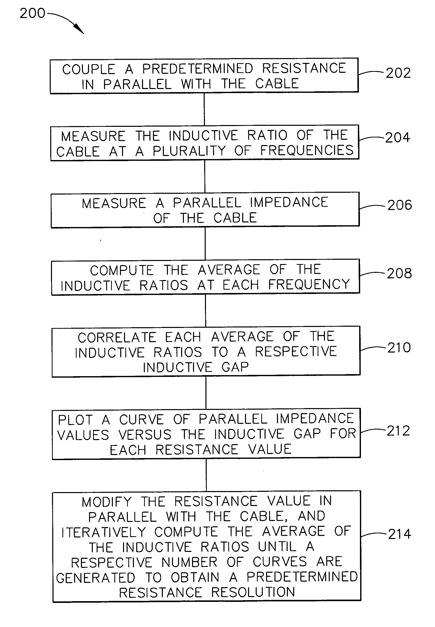
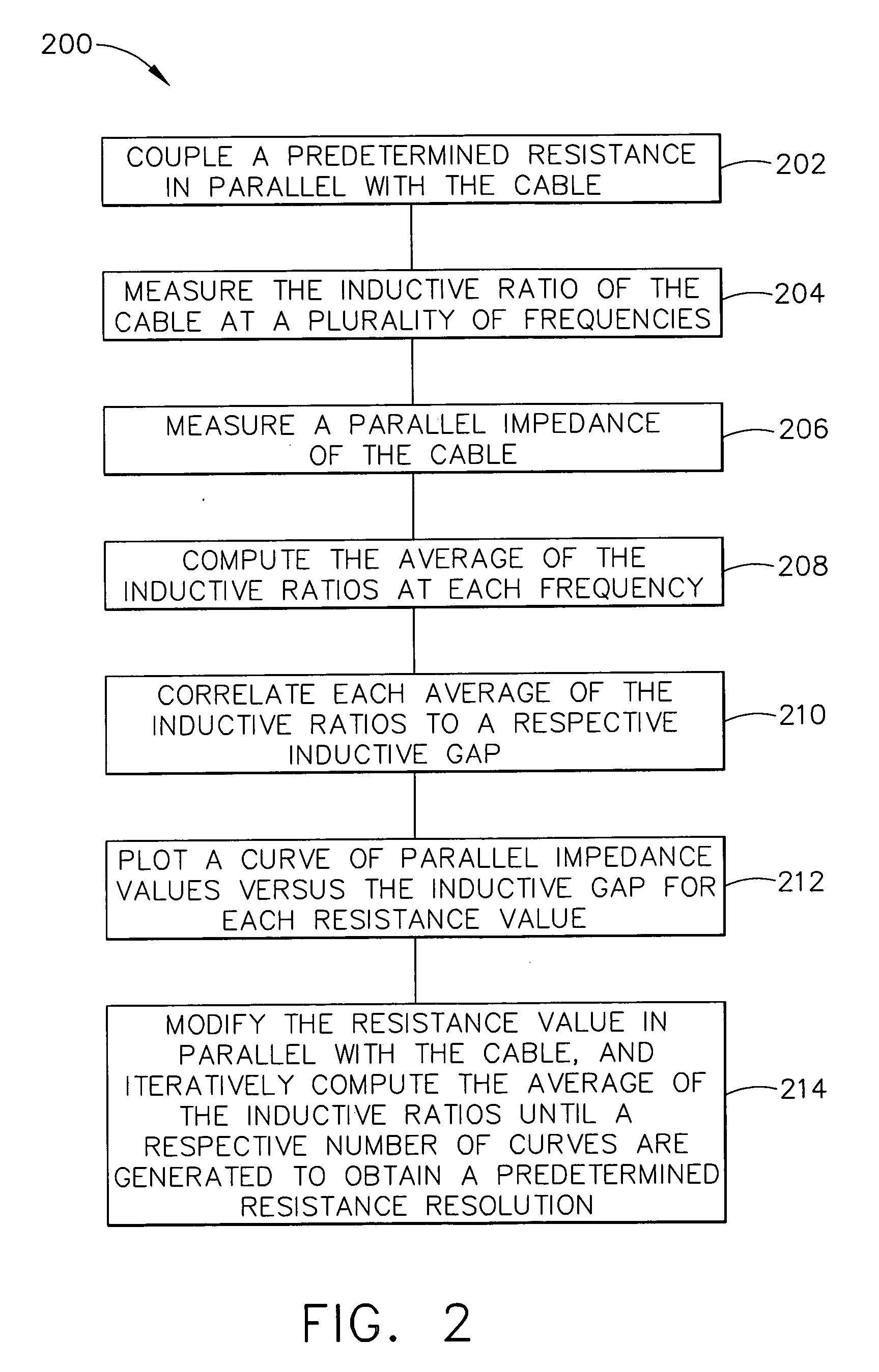
A method of testing a cable is provided. The method includes measuring at least one inductive ratio for the cable, determining an inductive gap from the at least one inductive ratio, measuring a parallel impedance of the cable, and determining a resistance of the cable based on the inductive gap and the parallel impedance.

Description

BACKGROUND OF THE INVENTION [0001] The present invention relates generally to a digital impedance measurement system and, in particular, to a digital eddy current system used to facilitate measuring inductive ratios. [0002] At least some known rotatable machines are monitored for a vibration using sensors that measure a change in displacement from a fixed position to a target fixed to a rotating member and / or from the rotating member itself. The sensors may be excited by conditioning circuitry to develop an output that is relative to a displacement and / or vibratory response of the target. The conditioning circuitry may be located remotely from the machine and sensor, and coupled to the sensor through one or more cables coupled together in series. At least some known systems include eddy current transducers to monitor proximity of a target to the transducer. The transducer is excited by the conditioning circuitry to interact with the target and such interaction causes a change in the...

Claims


Application Information

Patent Timeline
Patent Type & Authority Applications(United States)
IPC IPC(8): G01R31/08G01R31/02
CPCG01R31/021G01R31/58
Inventor HOYTE, SCOTT MORDINSLATES, RICHARD DALE
Owner BAKER HUGHES HLDG LLC
Why Eureka
Eureka Blog
Learn More