In the case of Japanese
Patent Application Publication No. 2002-166543, for example, it is sought to downsize a two-dimensional
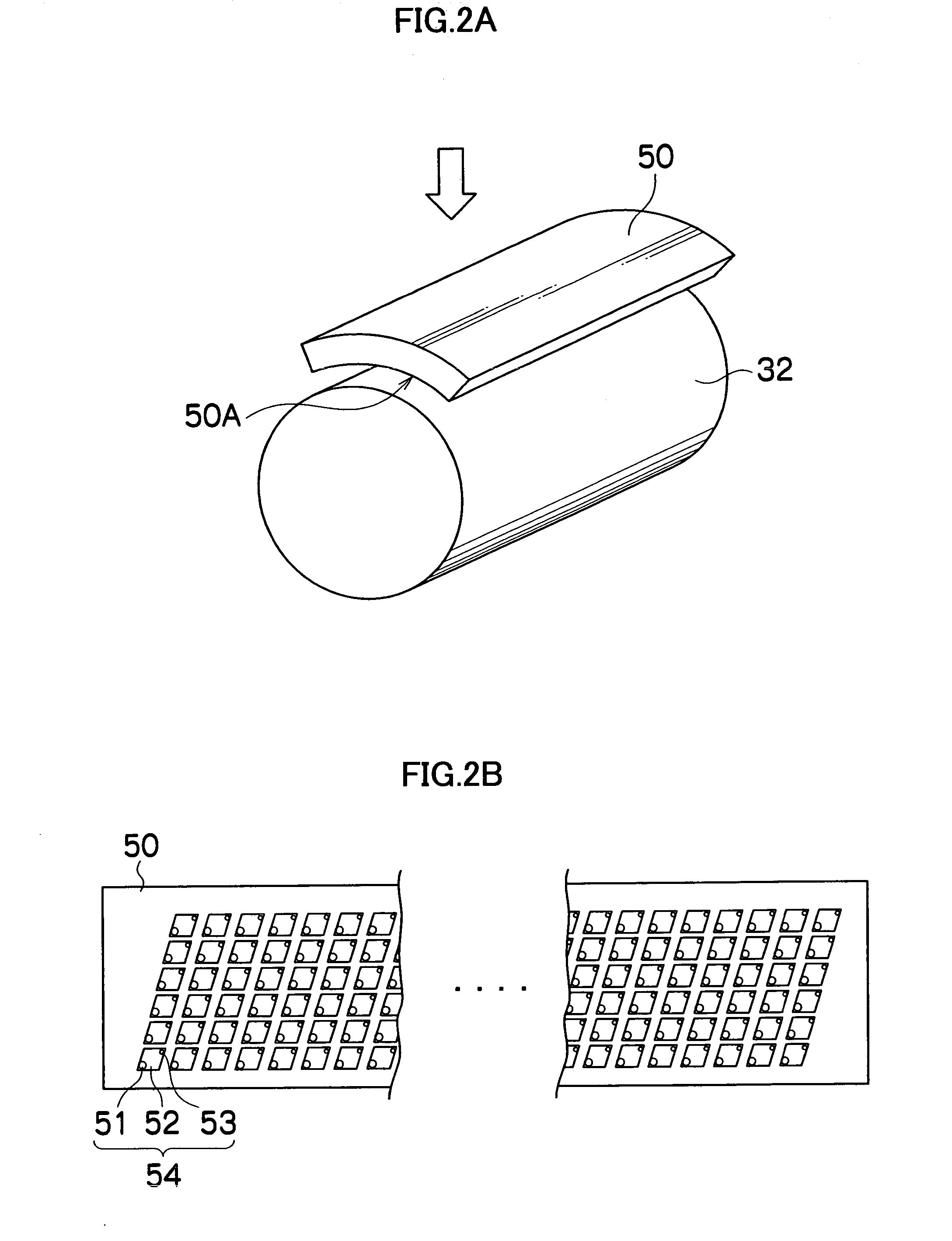
matrix type head by arranging
diamond-shaped pressure chambers at a
high density; however, in a matrix head for high-density recording in particular, recording is performed while the recording medium is conveyed, and hence any rotational deviation of the recording medium due to skewed travel, or the like (namely, the inclination of the conveyance direction of the recording medium with respect to the head) is liable to produce deviation in the positions of the ejected droplets, especially at the return sections in the matrix arrangement.
In this way, in an inkjet head in which the nozzles are arranged at
high density in a two-dimensional matrix configuration, if the recording medium is conveyed in a skewed fashion, then the positions of the dots formed on the recording medium become disarranged, thus causing band-shaped non-uniformities, and the like, and hence degrading the
image quality.
In addition to cases where the recording medium is conveyed in a skewed fashion, the same type of problem occurs in cases where the inkjet head is actually installed in an inclined fashion, since this has the similar positional relationship between the inkjet head and the recording medium.
Moreover, in a flat conveyance
system, the recording medium is liable to float up and / or become displaced, and therefore it is difficult to reduce the gap between the nozzles and the recording medium, and accordingly there may be large variation in the landing positions due to deviation in the flight of the droplets.
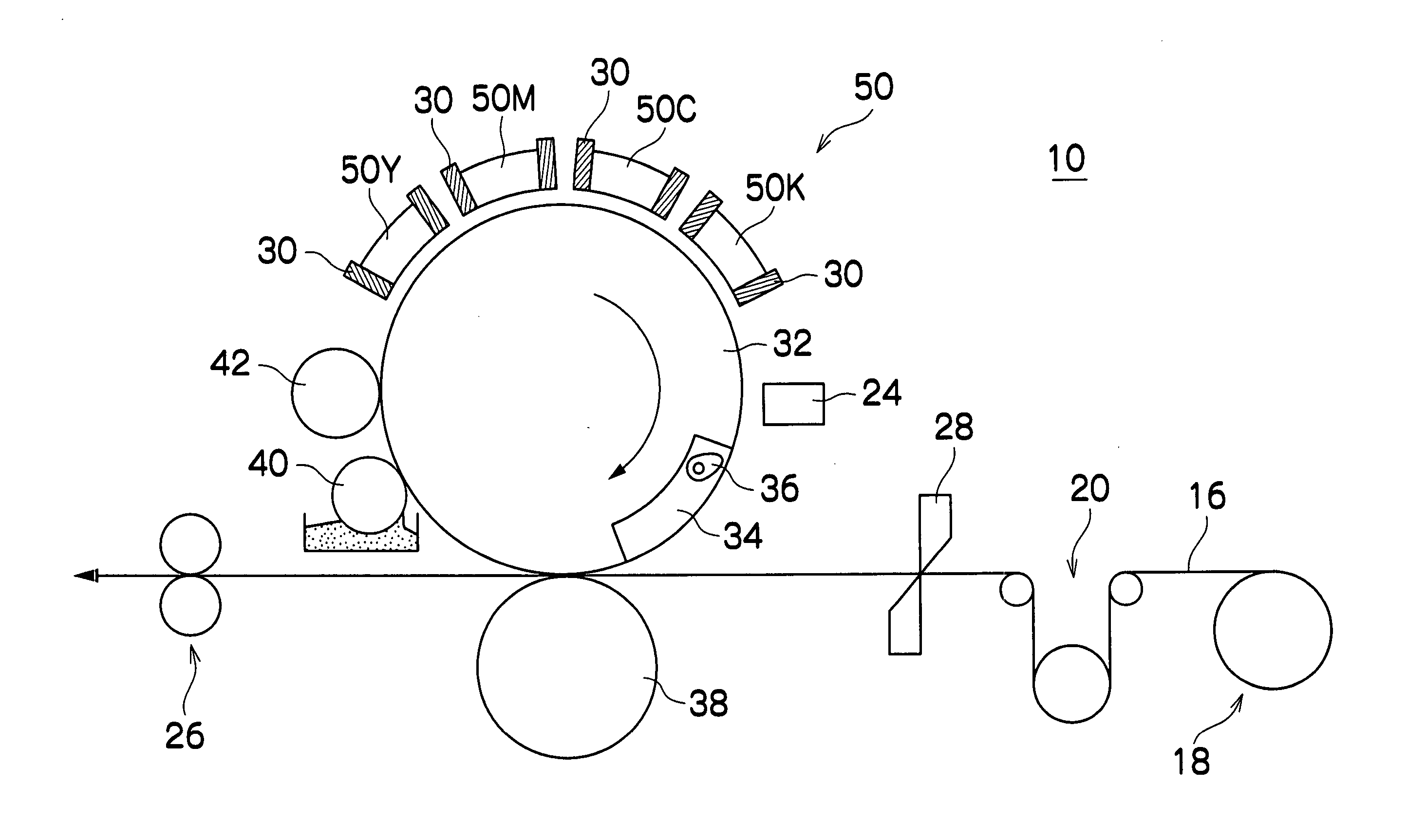
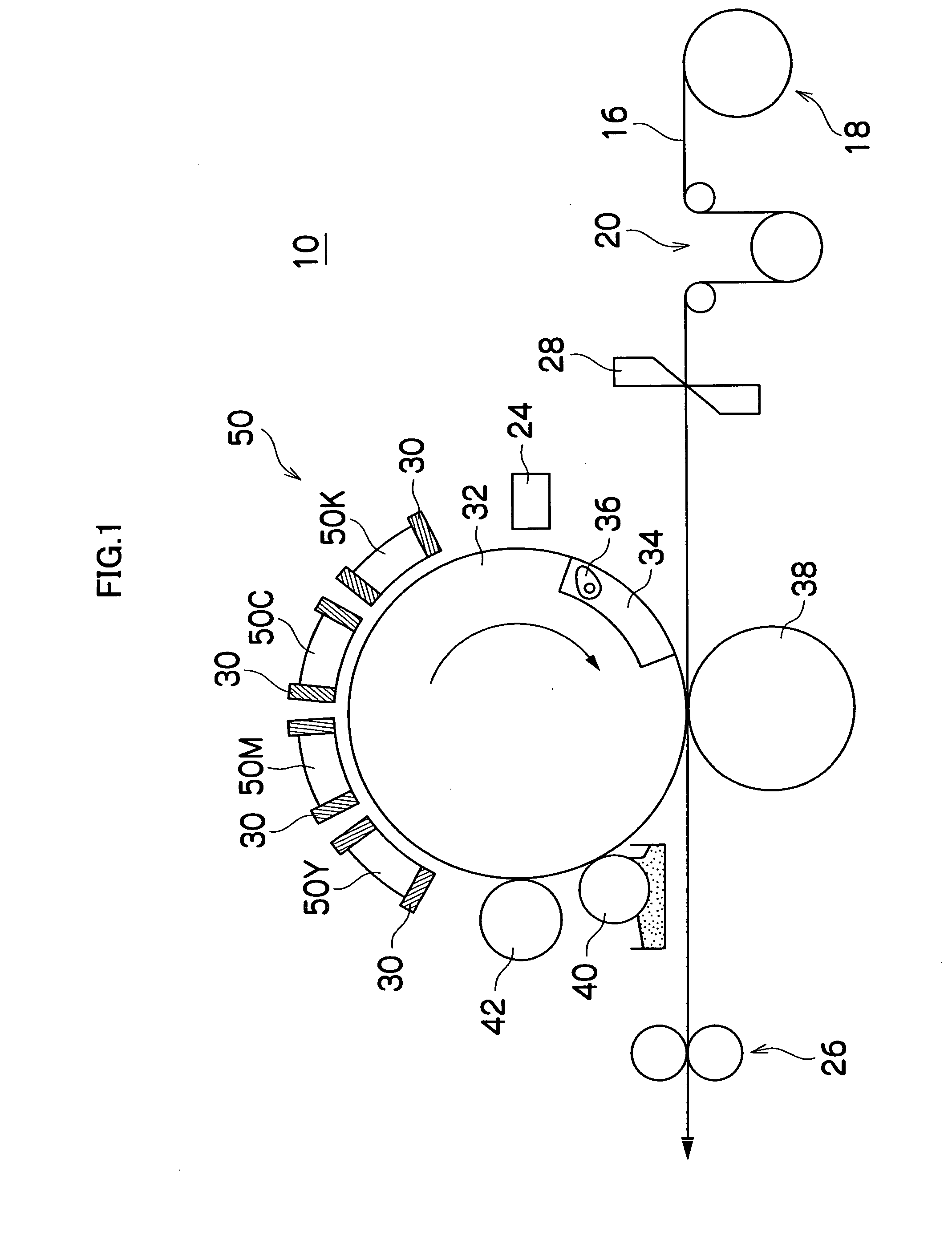
Furthermore, in Japanese
Patent Application Publication No. 2000-190535, the apparatus is made compact in size by disposing heads in the circumferential direction of a cylinder; however, this has a structure in which a line head is installed on a curved face-shaped member, and hence it is difficult to apply this composition to a
matrix type head in which a plurality of nozzles are arranged at
high density in a two-dimensional configuration.
Furthermore, Japanese
Patent Application Publication No. 2004-50449 seeks to achieve improved quality in the recorded image by providing a very fine liquid-repelling section on the surface of an intermediate transfer roller; however, in a line type head such as that shown in the embodiments,
semiconductor processing is required and it becomes difficult to achieve a long length head and high-speed operation.
In a head composed by joining together a plurality of short heads, non-uniformity is liable to occur at the joint section between the heads, and hence such heads are not suitable for high-quality recording.
Moreover, in a
matrix type head having a long, single-body structure, the head is required to have a prescribed length in the circumferential direction, and the gap between the drum and the nozzles is not uniform if the
nozzle surface of the head is a flat surface, and therefore, practical application is difficult.

