Back light unit and liquid crystal display employing the same

Inactive Publication Date: 2006-10-05
SAMSUNG ELECTRONICS CO LTD
View PDF9 Cites 64 Cited by
  • Summary
  • Abstract
  • Description
  • Claims
  • Application Information

AI Technical Summary

Benefits of technology

[0014] The present invention also provides a backlight unit including a reflection barrier wall ha

Problems solved by technology

However, a CCFL has a short lifetime and degrades color reproducibility.
Therefore, it is

Method used


Image

  • Back light unit and liquid crystal display employing the same
  • Back light unit and liquid crystal display employing the same
  • Back light unit and liquid crystal display employing the same

Examples


Embodiment Construction

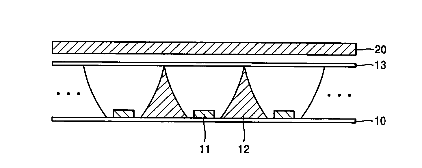
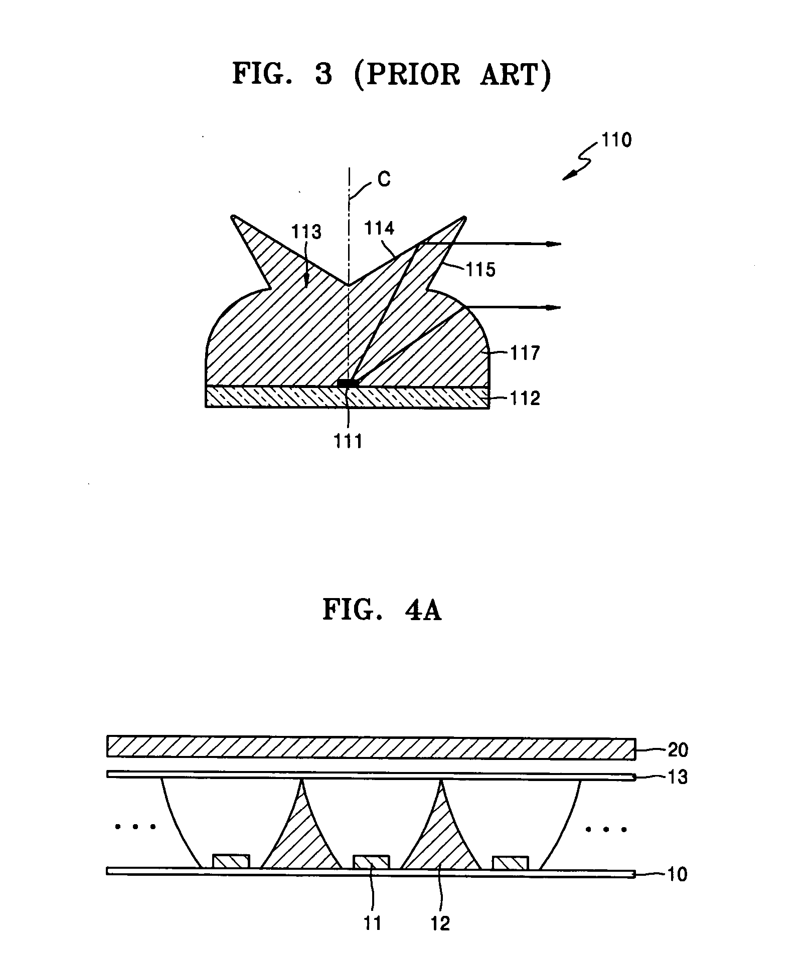
[0034]FIG. 4A is a cross sectional view of a liquid crystal display according to an exemplary embodiment of the present invention.

[0035] As shown in FIG. 4A, the liquid crystal display according to the present embodiment includes a liquid crystal panel 20 and a backlight unit disposed behind the liquid crystal panel 20. In general, the liquid crystal panel 20 has a bottom glass and a top glass, and liquid crystal is injected between the bottom glass and the top glass. The top glass and the bottom glass are sealed after injecting the liquid crystal. Any type of liquid crystal panel may be used in the present embodiment. The structure of the liquid crystal panel 20 is well known to those skilled in the art, so a detailed explanation thereof is omitted.

[0036] The backlight unit according to the present invention includes: a base plate 10; a plurality of point light sources 11 arranged on the base plate 10; a diffusion plate 13 which diffuses light emitted from the point light source ...


PUM


Abstract

A direct type backlight unit for improving high uniformity through a reflection barrier wall having a curved surface and a liquid crystal display employing the same are provided. The backlight unit includes: a base plate; a plurality of point light sources arranged in a plurality of lines on the base plate; a diffusion plate which diffuses light emitted from the plural of point light sources and generates a uniform light; and a reflection barrier wall, having a curved reflection surface, which reflects the light emitted from the point light source to the diffusion plate.

Description

CROSS-REFERENCE TO RELATED PATENT APPLICATION [0001] This application claims priority from Korean Patent Application No. 10-2005-0028067, filed on Apr. 4, 2005, in the Korean Intellectual Property Office, the disclosure of which is incorporated herein in its entirety by reference. BACKGROUND OF THE INVENTION [0002] 1. Field of the Invention [0003] Methods and apparatuses consistent with the present invention relate to a direct light type backlight unit including a reflection barrier wall having a curved surface for improving a uniformity and to a liquid crystal display employing the same. [0004] 2. Description of the Related Art [0005] A liquid crystal display (LCD) is a passive flat panel display that forms an image not using self-luminescence but using incident light from outside the LCD. A backlight unit is disposed behind the LCD to irradiate light toward a liquid crystal panel. [0006] Cold cathode fluorescence lamps (CCFLs) are generally used as light sources of backlight units...

Claims


Application Information

Patent Timeline
IPC IPC(8): F21V13/10H01L33/60
CPCG02B6/0031G02F1/133603G09G2320/0261G09G3/342G09G2310/024G02F1/133605G02F1/133622H01L33/60A47L13/225
Inventor NOH, JI-WHANSEONG, KI-BUM
Owner SAMSUNG ELECTRONICS CO LTD
Why Eureka
Try Eureka