Mitigating the effect of pulse distortions along an optical fiber communications link

a technology of optical fiber communication link and pulse distortion, applied in the field of mitigation, can solve the problems of failing, beginning to be an unacceptable risk of bit error, etc., and achieve the effect of optimizing the resulting pulse shape and mitigating the effect of deterministic pulse distortion

Inactive Publication Date: 2006-10-05
CORNING INC
View PDF5 Cites 5 Cited by
  • Summary
  • Abstract
  • Description
  • Claims
  • Application Information

AI Technical Summary

Benefits of technology

[0007] One aspect of the invention is a method of mitigating the effect of deterministic pulse distortions along an optical fiber communications link transmitting a train of pulses which comprises, at at least one point of the link, making plural copies of said pulse train, delaying each said copy by a different amount, coherently adding said copies to said pulse train, and adjusting the amplitude and phase of each said copy to optimize the resulting pulse shape.

Problems solved by technology

Such distortions accumulate along the transmission path, and can eventually reach a level at which there begins to be an unacceptable risk of bit errors, compelling regeneration of the pulses.
Conventional techniques for extending the path length have mostly been specific to one source of distortion: as for example, chromatic dispersion may be countered by the use of an appropriate length of fiber whose dispersion is opposite in sign to that of the main transmission fiber (dispersion-compensating fiber, DCF), and this may require several different treatments in succession, and may still fail if the distortions from different sources are interacting.

Method used


Image

  • Mitigating the effect of pulse distortions along an optical fiber communications link
  • Mitigating the effect of pulse distortions along an optical fiber communications link
  • Mitigating the effect of pulse distortions along an optical fiber communications link

Examples


Embodiment Construction

[0015] Reference will now be made in detail to the present preferred embodiment(s) of the invention, examples of which are illustrated in the accompanying drawings. Whenever possible, the same reference numerals will be used throughout the drawings to refer to the same or like parts.

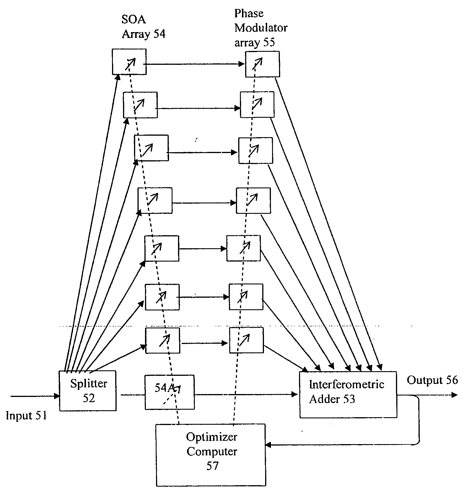
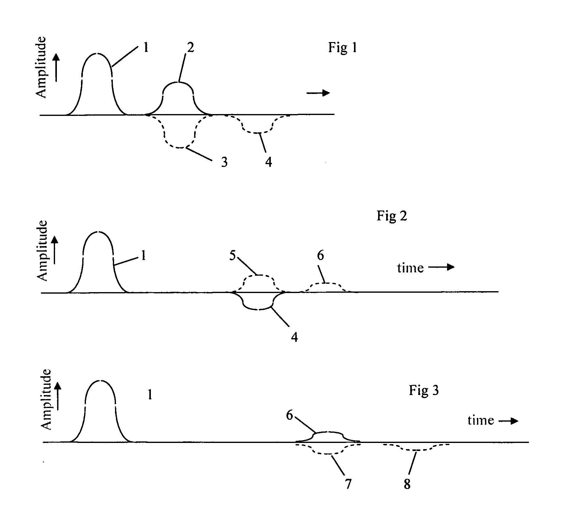
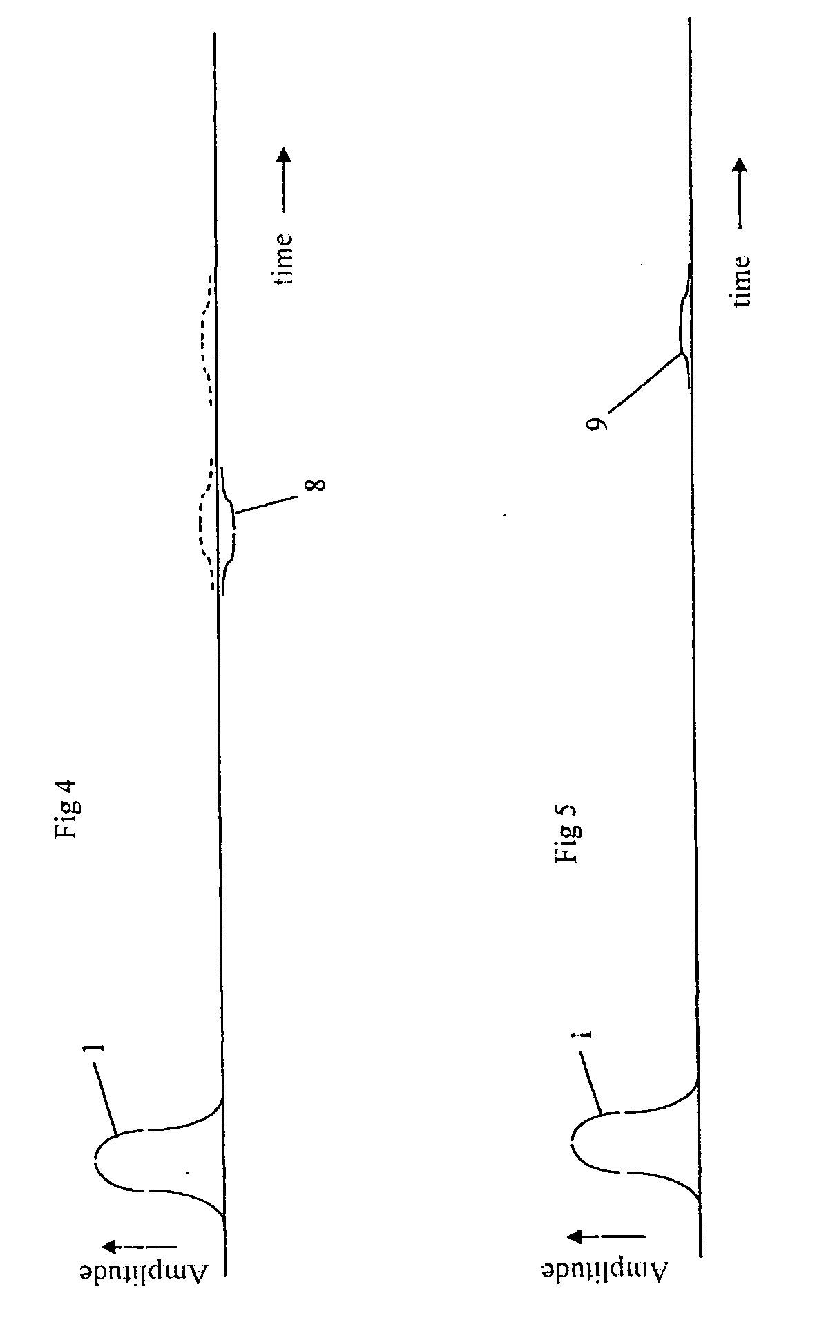
[0016] Referring to FIG. 11 or 12, an all-optical homodyne distortion compensator is shown. An input optical fiber 51 receives a modulated carrier signal having a distorted pulse train which resulted from propagation of the modulated carrier signal through an optical link. A first plurality of beam steering elements and couplers 52 split the distorted pulse train of the modulated carrier signal into multiple fractions or copies for guided or unguided propagation in waveguides or other beam steering elements, respectively. A parallel array of adaptive amplitude and phase controls 54 or 58 provide adjustable amplitude and phase of each of the copies of the distorted modulated carrier signal. A parallel co...


PUM


Abstract

A method of mitigating the effect of deterministic (only slowly changing) pulse distortions along an optical fiber communications link transmitting a train of pulses, and apparatus for performing it. Plural copies of the pulse train are made and are all coherently added together with the original train after delaying each copy by a different amount. The amplitude and phase of each copy are independently adjusted, normally by a computer, to optimize the resulting pulse shape. The technique is capable of mitigating (not totally eliminating) distortions of diverse origin, including but not limited to polarization mode dispersion, chromatic dispersion, multiple reflections, and self-phase modulation, even if they interact with each other.

Description

BACKGROUND OF THE INVENTION [0001] 1. Field of the Invention [0002] The present invention relates generally to a method of mitigating the effect of pulse distortions in a digital optical fiber communications link and to apparatus for implementing the method. More specifically, it relates to the mitigation of distortions that are deterministic in the sense that they are substantially the same as between one pulse and the next, though they may and almost always will vary significantly on a longer time-scale. [0003] 2. Technical Background [0004] Such deterministic distortions arise from a number of distinct and in some cases interacting causes, of which the most significant are usually polarization mode dispersion (PMD), chromatic or group-delay or group-velocity dispersion (GVD) self-phase modulation (SPM) and multiple reflections (MRN). [0005] Such distortions accumulate along the transmission path, and can eventually reach a level at which there begins to be an unacceptable risk of...

Claims


Application Information

Patent Timeline
Patent Type & Authority Applications(United States)
IPC IPC(8): G02B6/26H04B10/2507H04B10/508
CPCH04B10/508H04B10/2507
Inventor ELLIS, ANDREW DAVID
Owner CORNING INC
Why Eureka
Try Eureka