
Condensate scavenging system and method for in-ground vehicle lifts

a vehicle lift and condensate scavenging technology, which is applied in the direction of machines/engines, liquid fuel engines, positive displacement liquid engines, etc., can solve the problems of failure of the vehicle lift to operate, the condensate that collects in the base structure of the lift, and the various components of the vehicle li

Active Publication Date: 2006-10-05
SVI INT
View PDF4 Cites 4 Cited by
  • Summary
  • Abstract
  • Description
  • Claims
  • Application Information

AI Technical Summary

Benefits of technology

[0014] In one feature, the step of automatically removing includes removing the condensate in response to the lift moving between a raised and a lowered position....

Problems solved by technology

One problem associated with in-ground vehicle lifts is condensate that collects in the base structure of the lifts.
If it is not removed from the base structure, the condensate will typically cause corrosion, potentially severe, of the various components of the vehicle lift.
Such corrosion is a continuing problem at vehicle service centers that employ in-ground lifts because it causes failures in operation of the lifts, downtime, and costly repairs.
While this approach may work, it is labor intensive and requires a regular maintenance schedule to insure that the condensate is periodically removed from each in-ground lift of the service center before the condensate can produce undesirable amounts of corrosion.

Method used


Image

  • Condensate scavenging system and method for in-ground vehicle lifts
  • Condensate scavenging system and method for in-ground vehicle lifts
  • Condensate scavenging system and method for in-ground vehicle lifts

Examples


Embodiment Construction

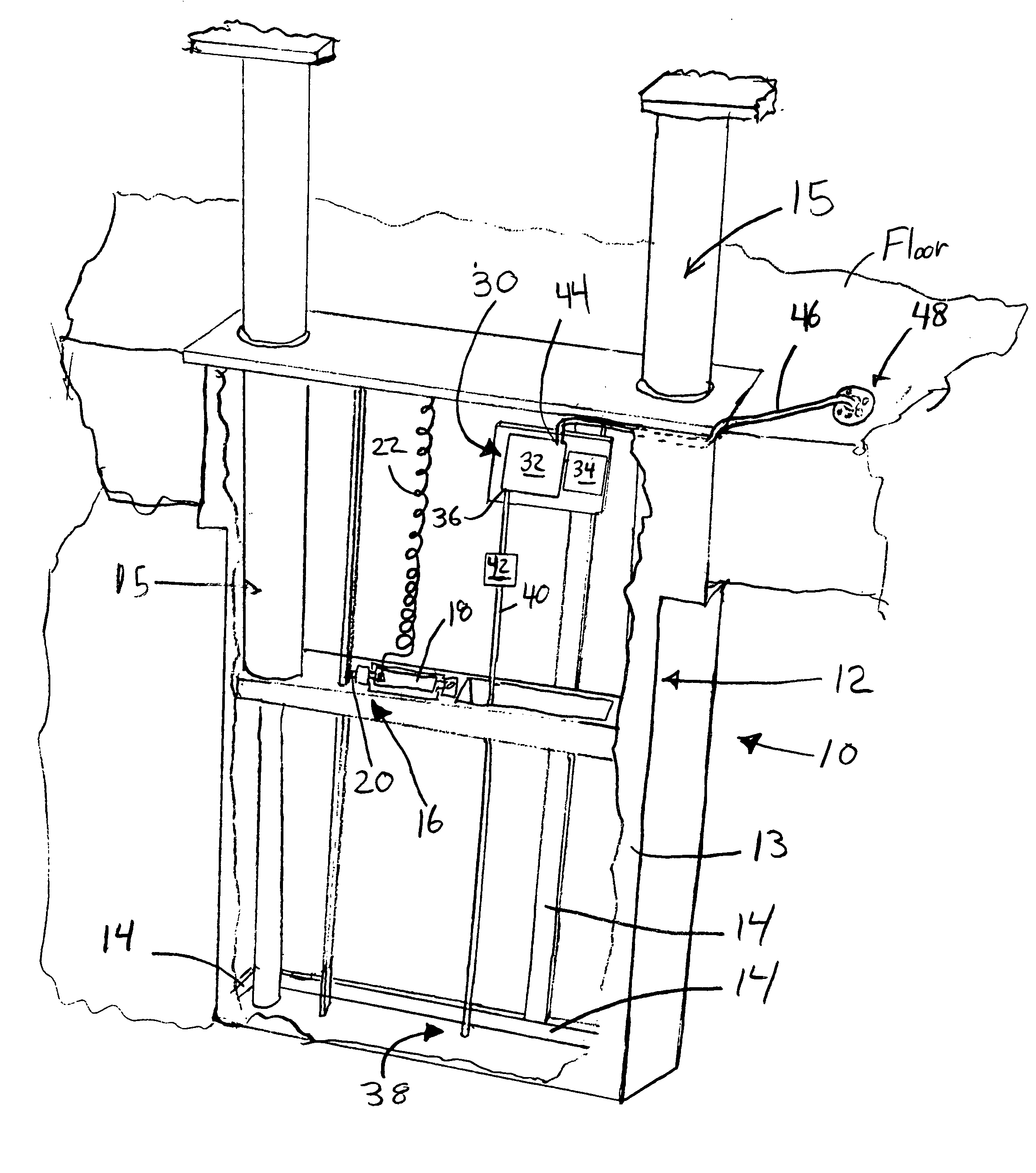
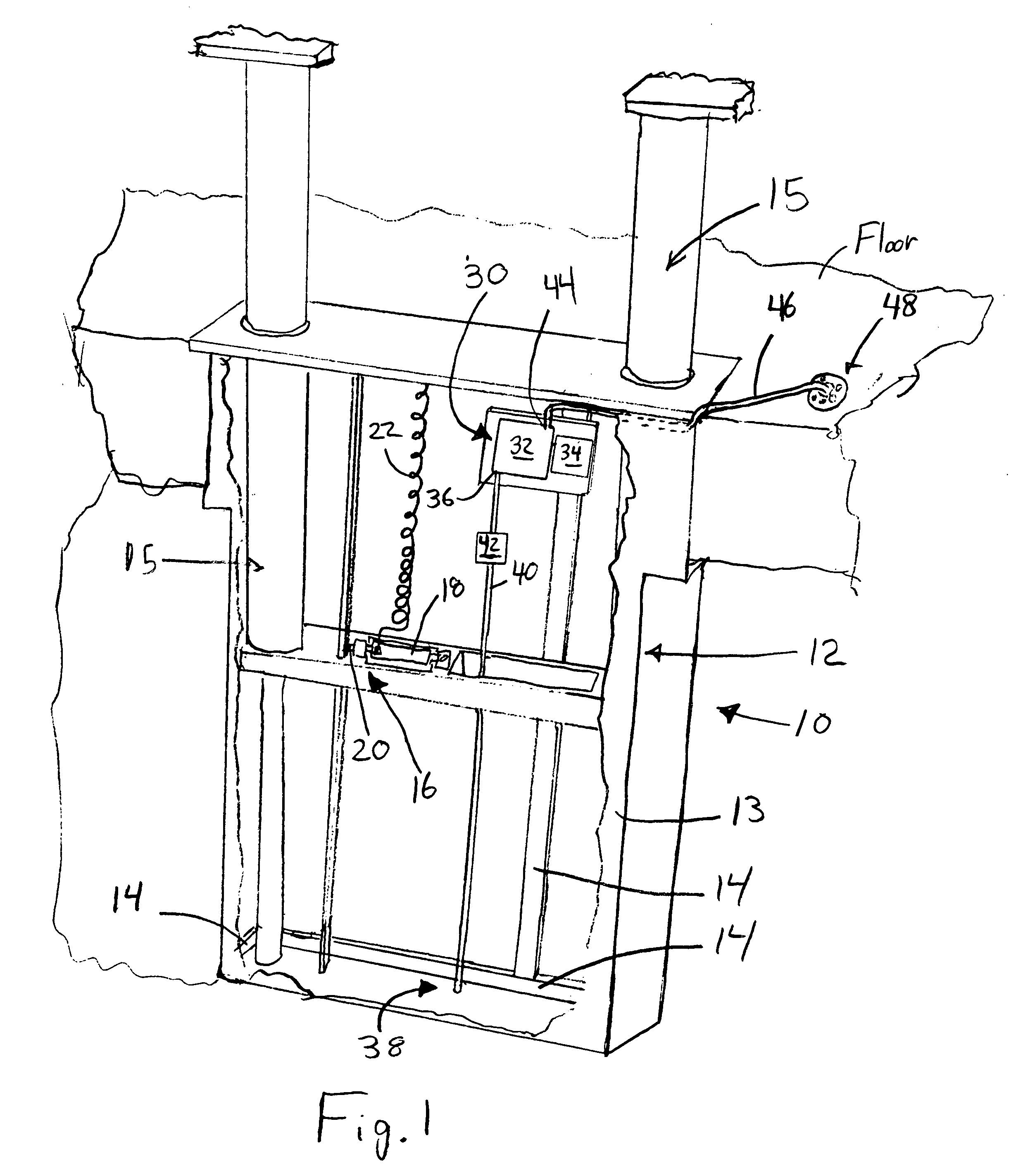
[0022] One example of an in-ground vehicle lift is shown in FIG. 1 in the form of a in-ground cassette lift 10. The lift 10 includes a base structure or frame 12 that is received in a conforming pit that is formed into the floor of the vehicle service center that utilizes the lift 10. The base structure 12 typically includes a case or housing structure 13 and structural frame members 14 that mount the components of the lift 10, including one or more hydraulic lift cylinders 15, a pneumatically actuated safety lock mechanism, shown somewhat diagrammatically at 16, which includes a pneumatic cylinder 18 that actuates a safety latch 20, and a compressed air line 22 for selectively supplying air to the cylinder 18 to disengage the safety latch 20 when the lift 10 is to be lowered. Because the specific details of the lift 10 and its components are not critical to an understanding of the invention, and further because there are many well known types and constructions for in-ground vehicle...


PUM


Abstract

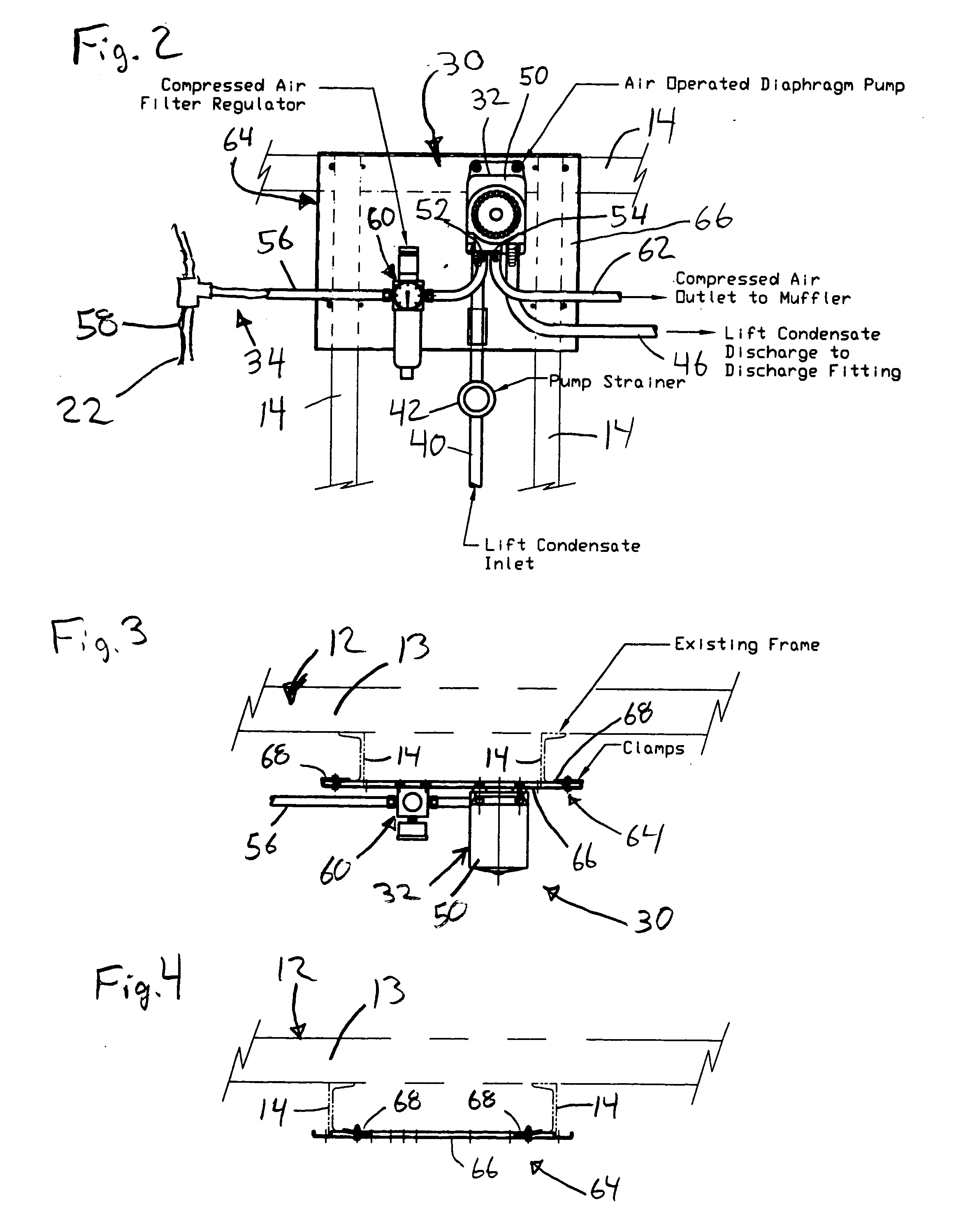
An in-ground lift (10) is provided with a condensate scavenging system (30) that includes a pump (32) and a control (34) that is connected to the pump (32) and configured to selectively switch the pump (32) between a non-pumping state wherein the pump (32) is inactive and a pumping state wherein the pump (32) is expelling condensate from the base structure (12) of the lift (10). It is preferred that the control (34) be configured so that the pump (32) automatically switches between the non-pumping state and the pumping state in response to a predetermined change of state in the in-ground vehicle lift (10).

Description

FIELD OF THE INVENTION [0001] This invention relates to vehicle lifts and, more particularly to in-ground vehicle lifts such as in-ground cassette lifts, in-ground high pressure lift cylinder tubes, in-ground side-by-side lift equalizer tubes, or in-ground continuous pit truck and buss movable piston axle engaging type lifts. BACKGROUND OF THE INVENTION [0002] One problem associated with in-ground vehicle lifts is condensate that collects in the base structure of the lifts. Typically, this condensate is generated every time the lift is cycled up and down, which draws fresh air and the moisture contained therein into the base structure of the lift. Condensate then forms when the air contacts the cool surfaces in the base structure of the lift. If it is not removed from the base structure, the condensate will typically cause corrosion, potentially severe, of the various components of the vehicle lift. Such corrosion is a continuing problem at vehicle service centers that employ in-gro...

Claims


Application Information

Patent Timeline
IPC IPC(8): F04B53/00
CPCB66F7/16B66F7/28F04B2207/043F04B43/073F04B49/02B66F17/00
Inventor CLIMENHAGA, DOUGLAS W.LEAHY, THOMAS F.
Owner SVI INT
Learn More