Mehotd for determining a maximum power point voltage of a fuel cell, as well as fuel cell control system and power controller used in the fuel cell control system

a technology of power point voltage and fuel cell, which is applied in the direction of process and machine control, electrochemical generators, instruments, etc., can solve the problem of inability of fuel cells to generate high-output power, and achieve the effect of reducing the output power of fuel cells

Inactive Publication Date: 2006-10-05
HITACHI LTD
View PDF2 Cites 142 Cited by
  • Summary
  • Abstract
  • Description
  • Claims
  • Application Information

AI Technical Summary

Benefits of technology

[0023] When a temperature terminal that can receive the temperature detection value of the fuel cell is further provided, the control signal generating means compares the temperature detection value received at the temperature terminal with a preset temperature value and generates the above control signal so as to reduce the output power of the fuel cell when the temperature detection value of the fuel cell exceeds the preset temperature value.

Problems solved by technology

In the technology described in the Japanese patent Laid-open No. 2003-229138, however, the voltage setting is determined by limiting the output voltage when the fuel cell generates power at the maximum power point (this output voltage is called the maximum power point voltage) to the range of 35% to 50% of the open-circuit voltage; this is problematic because, for some fuel cells, the output power cannot be limited to or below the maximum power point.
In this case, as indicated by characteristic curve “b” that represents a current-power density characteristic, the output power greatly deviates from the maximum power point Q, resulting in the inability of the fuel cell to generate high-output power.

Method used


Image

  • Mehotd for determining a maximum power point voltage of a fuel cell, as well as fuel cell control system and power controller used in the fuel cell control system
  • Mehotd for determining a maximum power point voltage of a fuel cell, as well as fuel cell control system and power controller used in the fuel cell control system
  • Mehotd for determining a maximum power point voltage of a fuel cell, as well as fuel cell control system and power controller used in the fuel cell control system

Examples


first embodiment

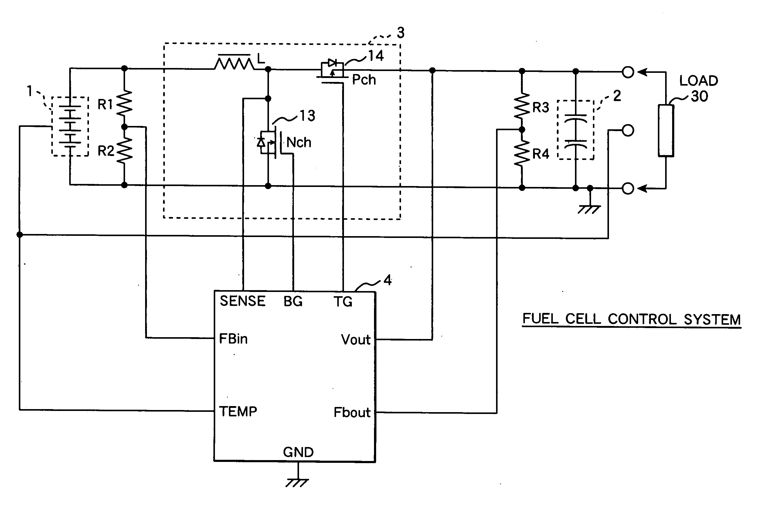
[0051]FIG. 4 shows an exemplary structure of a fuel cell control system according to a first embodiment of the present invention. The fuel cell control system mainly comprises a fuel cell 1, an electric double layer capacitor (EDLC) 2, which is a storage means, a circuit section 3, which is a step-up or step-down converter, and a control IC chip (power controller) 4 that performs switching control for the circuit section 3. The fuel cell control system is used in a mobile electronic apparatus. The fuel cell 1 is a direct methanol fuel cell.

[0052] In the fuel cell control system, the dielectric strength of the electric double layer capacitor 2 used as the storage means is 2.3 V to 3.3 V per cell. When two cells are connected in series as shown in FIG. 4, the dielectric strength is 4.6 V or higher, so the electric double layer capacitor 2 can be used in mobile telephones, personal digital assistants (PDAs), digital still cameras, multi-media players, and other electronic apparatus th...

second embodiment

[0082]FIG. 8 shows the structure of a fuel cell control system according to a second embodiment of the present invention. The fuel cell control system uses a control IC chip 4a, the internal structure of which differs from that of the IC chip 4 in the fuel cell control system according to the first embodiment shown in FIG. 6. The structures of the circuit section 3a and other parts are the same as in the fuel cell control system shown in FIG. 6.

[0083] The control IC chip 4a comprises a control section 11a and reference voltage setting section 12. The output voltage of the circuit section 3a is divided by the resistor R3 and resistor R4, input to the stored voltage terminal Fbout, and then compared with the second reference voltage Vref2 by the differential amplifier S3. The differential voltage (referred to below as the output voltage difference) is output to a terminal of the reference voltage setting section 12. The temperature voltage of the fuel cell 1 is input from the tempera...

third embodiment

[0092]FIG. 10 shows the structure of a fuel cell control system according to a third embodiment of the present invention. The fuel cell control system according to the third embodiment shown in FIG. 10 differs from the fuel cell control systems according to the first and second embodiments in that the circuit section 3b is a step-up chopper circuit using a Schottky barrier diode 15 rather than being of the synchronous rectification type. Specifically, in the circuit section 3b in FIG. 10, the Schottky barrier diode 15 is substituted by the P-channel power MOSFET 14 in the circuit section 3a in FIG. 6. This structure is more useful for increasing the voltage at the output end than the structure according to the first embodiment in FIG. 6 and the structure according to the second embodiment in FIG. 8.

[0093] The control IC chip 4b according to the third embodiment shown in FIG. 10 will be described in detail. Unlike the control IC chip 4 according to the first embodiment shown in FIGS...


PUM

PropertyMeasurementUnit
open circuit-voltageaaaaaaaaaa
current-voltage characteristicaaaaaaaaaa
voltageaaaaaaaaaa

Abstract

A detection voltage, which is obtained by dividing the voltage of a fuel cell 1 by resistors, is compared with a first reference voltage Vref1 by a differential amplifier. The differential voltage is input to a control section. The control section performs PWM control for the circuit section according to the difference. The first reference voltage Vref1 is set according to the dividing ratio of the resistors, based on the output voltage when the fuel cell generates power at the maximum power point. To determine the output voltage for maximum power generation, a characteristic curve representing a current-voltage characteristic is approximated by an approximating line within a range excluding an area in which the output voltage changes abruptly when the output current is nearly zero, and an extrapolated voltage is obtained on the extension line of the approximating line at an output current of zero. Fifty percent of the extrapolated voltage is then determined as the output voltage when the fuel cell generates power at the maximum power point. Thus, a fuel cell control system that identifies a highly precise output voltage for power generation at a maximum power point and controls power so that the maximum power point is not exceeded could be provided.

Description

CLAIM OF PRIORITY [0001] The present application claims priority from Japanese application serial no. 2005-104875, filed on Mar. 31, 2004, the content of which is hereby incorporated by reference into this application. FIELD OF THE INVENTION [0002] The present invention relates to a method for determining a maximum power point voltage of a fuel cell, as well as a fuel cell control system and a power controller used in the fuel cell control system. BACKGROUND OF THE INVENTION [0003] Recent progress in electronic technology is rapidly making the widespread use of mobile electronic apparatus such as mobile telephones, notebook computers, audio-visual apparatus, and mobile terminals. Owing to development of active cell materials and high-capacity cell structures, secondary cells used as power supplies of these mobile electronic apparatus have evolved from conventional seal lead batteries to Li-ion batteries through Ni—Cd batteries and Ni-hydrogen batteries to increase their capacities. ...

Claims


Application Information

Patent Timeline
Patent Type & Authority Applications(United States)
IPC IPC(8): H01M8/04G05D11/00
CPCH01M8/04007Y02E60/50H01M8/04559H01M8/04567H01M8/04597H01M8/04619H01M8/04626H01M8/0488H01M8/04888H01M8/0494H01M8/04947H01M8/1011H01M2008/1095Y02E60/523H01M8/04365
Inventor NORIMATSU, YASUAKIKANOUDA, AKIHIKOKIKUCHI, MUTSUMI
Owner HITACHI LTD
Why Eureka
Try Eureka