

Piezoelectrically stimulated article
a technology of electric stimulation and articles, applied in the field of self-contained articles, can solve the problems of complex circuitry of devices and the increase of the complexity of electrotherapy devices
- Summary
- Abstract
- Description
- Claims
- Application Information
AI Technical Summary
Problems solved by technology
Method used
Image

Examples
example 1
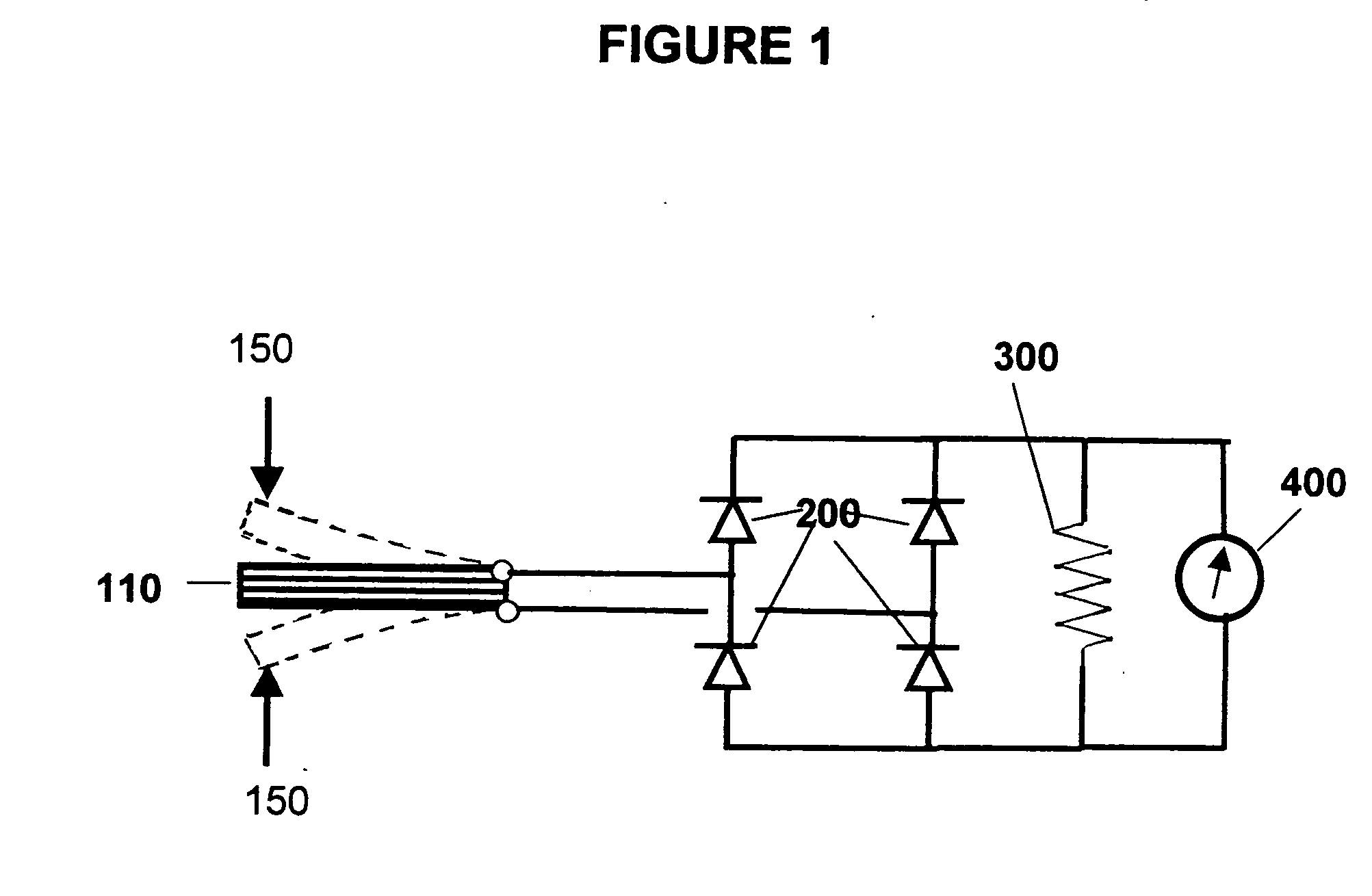
[0036] This example was a test of the inventive concept applied to a model system.
[0037]FIG. 1 schematically illustrates the model system having piezoelectric element 110, an electrical circuit connecting the piezoelectric element to a bridge rectifier 200 and then to one megaohm resistor 300 and a voltmeter 400. The piezoelectric element consisted of a bimorph (two layer) PZT (lead zirconium titanate) fiber array having dimensions of 12.7 cm length×1.27 cm width and 0.127 cm thickness obtained from Advanced Cerametrics, Inc., Lambertville, N.J. The piezoelectric fiber array was mounted as a cantilever beam and the free end of the beam was subjected to ±1.90 cm amplitude displacement at a frequency of 10 Hz by a sinusoidal force 150 having a peak amplitude of 227 grams.
[0038] The diodes of the rectifier 200 were of a very low leakage type CMPD6001S manufactured by Central Semiconductor Corp, Hauppauge N.Y. The one megaohm resistor simulated the dry skin impedance of a human body. ...
example 2
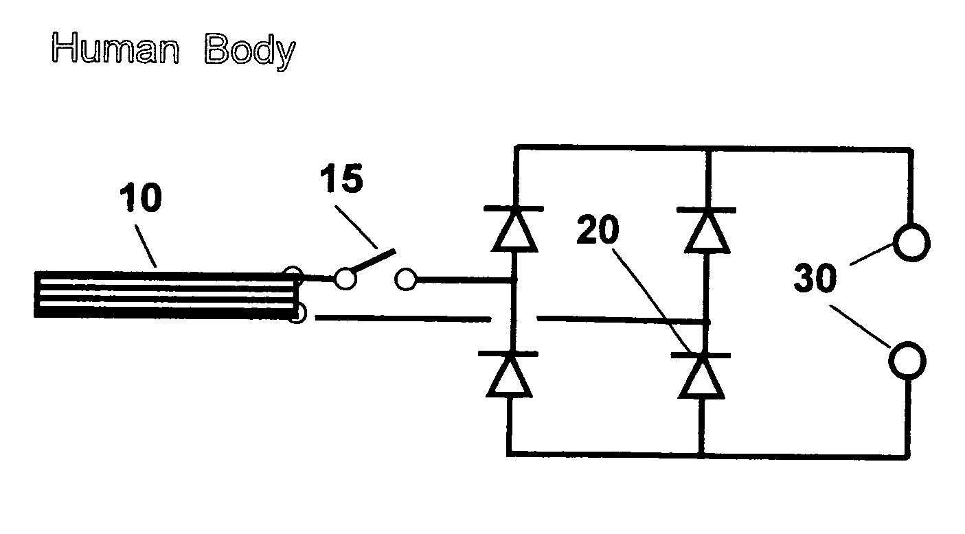
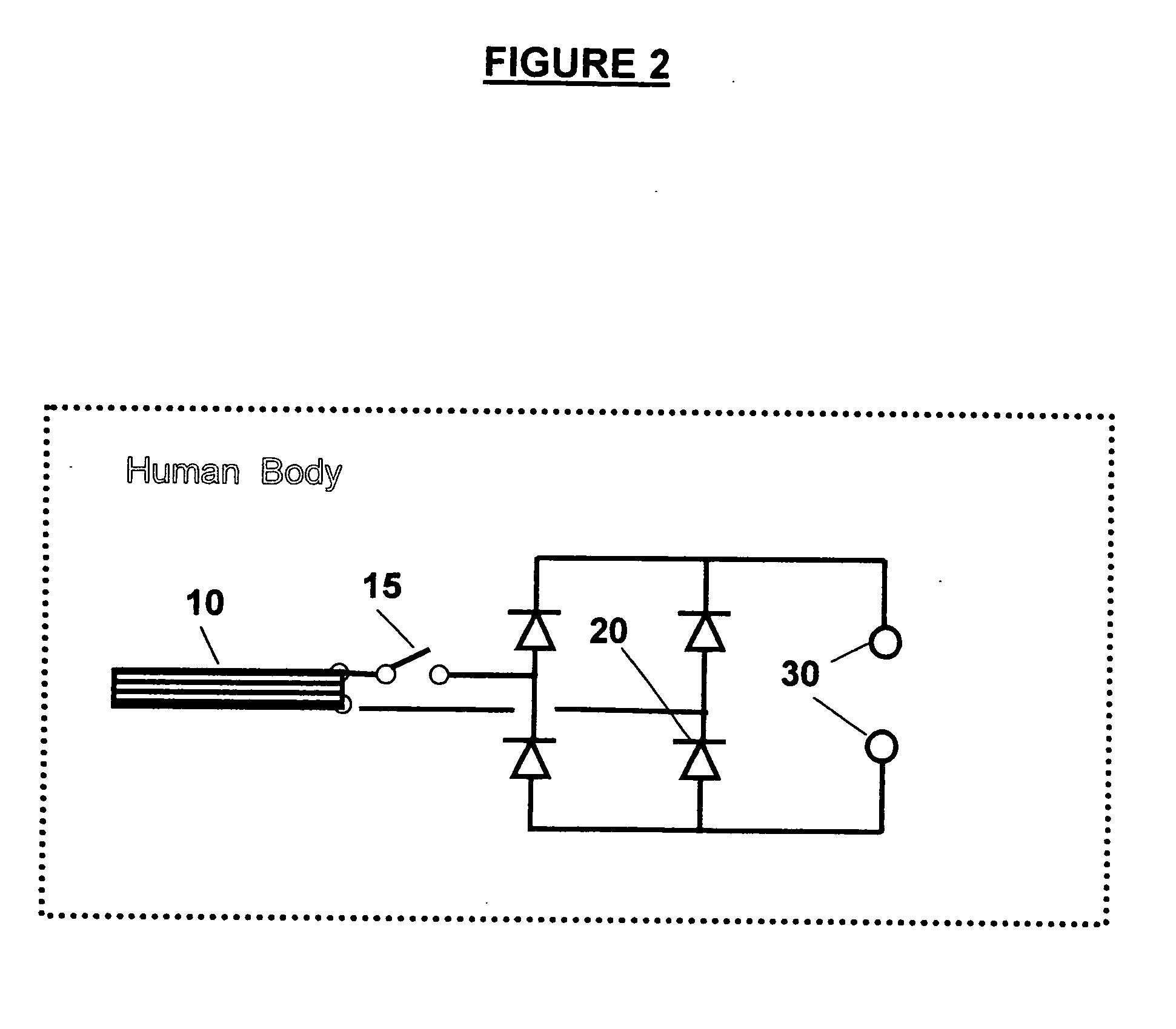
[0040] An article of the invention comprising the device of the invention illustrated in FIG. 2 is worn on a part of a human body selected from the neck, shoulder, elbow, wrist, hand, back, knee, ankle, chest, abdomen, leg and foot. The article of the invention may be attached to the body part by an elasticized fabric (not shown). The piezoelectric element of the device 10 is actuated by the motion of that body part and produces an electrical potential. The piezoelectrical element is connected through an optional on-off switch 15 to a full-wave rectifier bridge consisting of low leakage diodes 20 and thence to a pair of electrodes 30. When the circuit is closed, random motion of the body part produces an electrical potential at the electrodes 30 of full-wave rectified pulses of random frequency and amplitude. The electrodes 30 are in contact with a human body that receives the electrical power. The human body actuating the piezoelectric element need not be the human body in contact ...
example 3
[0041] An article of the invention comprising the device of the invention illustrated in FIG. 3 is worn on a part of a human body selected from the neck, shoulder, elbow, wrist, hand, back, knee, ankle, chest, abdomen, leg and foot. The article of the invention may be attached to the body part by an elasticized fabric (not shown). The piezoelectric element of the device 10 is actuated by the motion of that body part and produces an electrical potential. The piezoelectric element is connected to a circuit that stores and modifies the electrical potential and delivers it to electrodes 30. The electrodes 30 are in contact with a human body that receives the electrical power. The human body actuating the piezoelectric element need not be the human body in contact with the electrodes.
[0042] The circuit comprises an optional on-off switch 15, diodes 23, 24, 25, 26, capacitor 40, a Zener diode 45, a silicon controlled rectifier (SCR) 50 and resisters R1, R2, and R3. Preferred elements for...
PUM
 Abstract
Description
Claims
Application Information