
Business application development and execution environment

a technology of execution environment and business application, applied in the field of business application development and execution environment, can solve problems such as difficult communication to occur

Active Publication Date: 2006-10-05
IVANTI INC
View PDF17 Cites 209 Cited by
  • Summary
  • Abstract
  • Description
  • Claims
  • Application Information

AI Technical Summary

Benefits of technology

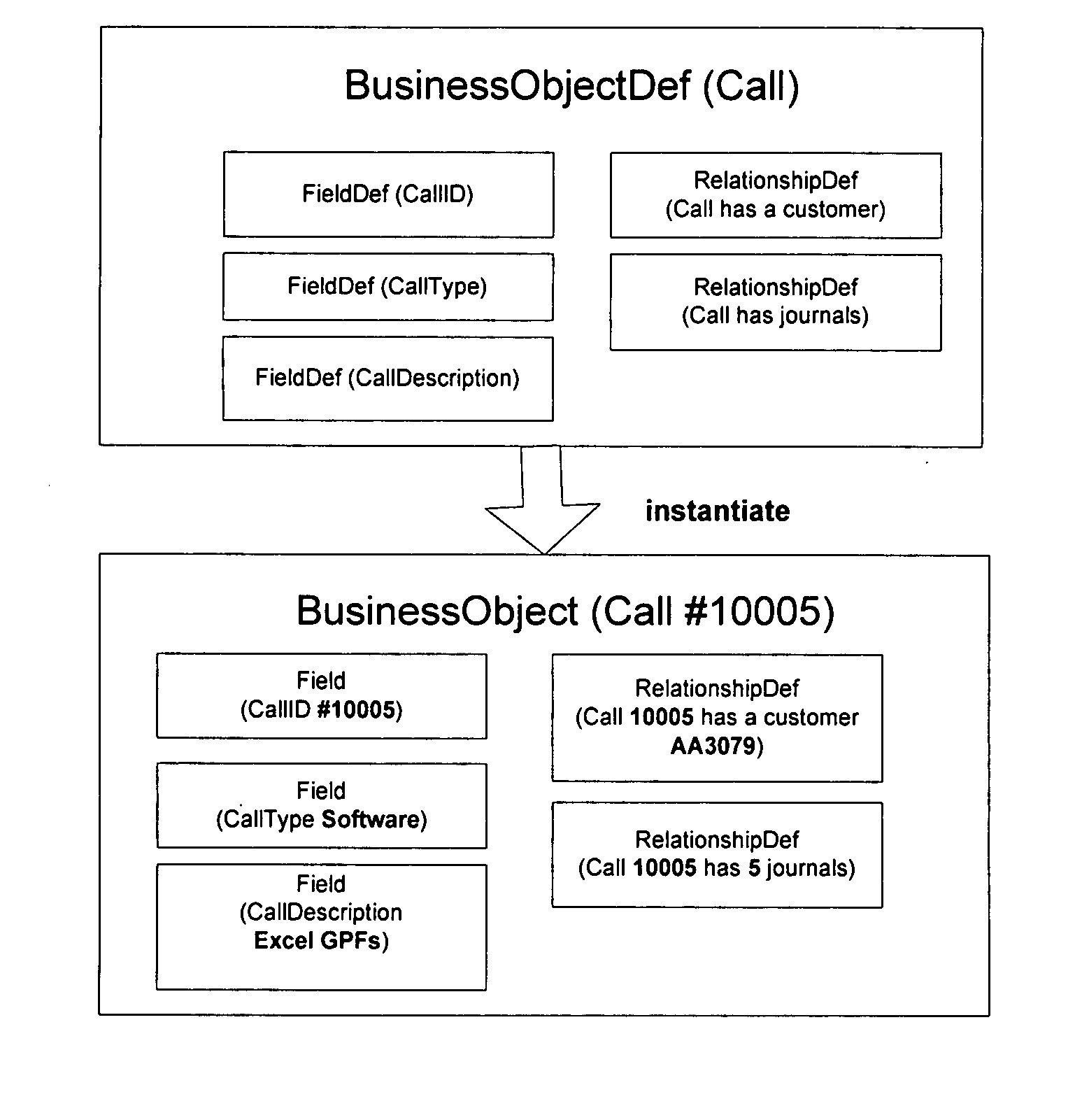
[0043] The fact that business objects are definitional makes these business objects very powerful yet simple. Specifically, it is possible to create very complex business objects without writing any code. Since the business objects of the present invention do not operate directly with a database means that the business objects can run on any tier within an n-tier system without any changes. This means that the business object logic can operate appropriately whether to provide feedback to a GUI-based client or to validate data coming into a server. Defining Business Objects
[0346] 6. Select to link child records to their parent via the standard constraint. Note that the standard constraint is the typical relationship constraint. It facilitates the link between parent and child by creating a Parent Link field, housed in the child (Workorder), which stores the parent's RecID. 7. Click Next to bring up the Name and Description page. 8. Accept the default Relationship name and Display name; the Display name appears in the navigator bar under the object's Relationships heading. 9. In the Description text box, type Relates the Workorder child object to the Service parent object. Click Next to bring up the Confirmation page.

Problems solved by technology

Although made business software applications are designed to communicate with each other, getting the communication to occur can be very difficult.

Method used


Image

  • Business application development and execution environment
  • Business application development and execution environment
  • Business application development and execution environment

Examples


Embodiment Construction

[0004] A methods and apparatuses for implementing a business application development and execution environment are disclosed. In the following description, for purposes of explanation, specific nomenclature is set forth to provide a thorough understanding of the present invention. However, it will be apparent to one skilled in the art that these specific details are not required in order to practice the present invention. For example, although the present invention has been described with reference to specific data communication and storage standards, the same techniques can easily be applied to other types of data communication and storage standards.

Definitions

[0005] The disclosed invention is related to and operates with many existing technologies. As is common in the computer industry, technical acronyms are often used to identify known technologies in this document. This section provides a list of acronym definitions and technology descriptions in order to familiarize the read...


PUM


Abstract

A business application development environment and a corresponding business application execution environment is disclosed. A graphical user interface based Workflow Designer allows a user to easily create business applications graphically. The business applications are converted into the Business Process Modeling Language (BPML). Existing BPML applications may also be edited with the graphical user interface BMPL designer of the present invention. Created business applications (that are represented in BPML) can then be hosted on any XML based web services server system. Business applications generally operate on business objects. The objects allow for fields to include functions that combine other fields. Once an application has been designed, the BPML code may be executed using a BPML execution engine. The BPML execution engine executes the BPML based applications. One embodiment interprets BPML applications with an interpreter in the execution engine. Another embodiment compiles the BPML applications into directly executable code.

Description

RELATED APPLICATIONS [0001] The present patent application hereby incorporates by reference in its entirety and claims the benefit of the previous U.S. Provisional Patent Application entitled “Business Application Development and Execution Environment” filed on Oct. 29, 2004 having Ser. No. 60 / 623,768.FIELD OF THE INVENTION [0002] The present invention relates to the field of software application development and execution environments. In particular the present invention discloses a business software application development and execution environment that allows users to easily develop business applications using a graphical user interface and the developed business applications may easily access other data from legacy systems. BACKGROUND OF THE INVENTION [0003] Businesses typically use a wide variety of different software products. Although made business software applications are designed to communicate with each other, getting the communication to occur can be very difficult. Furth...

Claims


Application Information

Patent Timeline
IPC IPC(8): G06F9/44
CPCG06Q10/10G06F8/10
Inventor KLERK, ADRIAN DECOHEN, MICHAELFUKAYA, SAGIRIZAKHARCHENKO, SERGEYTURPEN, RICHARDALAGARSAMY, TASPA
Owner IVANTI INC
Learn More