Television Signal Reception Apparatus and Method, and Broadcast Reception Apparatus and Method

a television signal and reception apparatus technology, applied in the field of function operation technique of can solve the problems of affecting the viewing of programs, the proposal will not be very effective for a television signal reception apparatus for which the number of functions is expected to be increased, and the use of tediousness, etc., to achieve simple and easy operation, improve the effect of user interfa

Inactive Publication Date: 2006-10-05
CANON KK
View PDF9 Cites 13 Cited by
  • Summary
  • Abstract
  • Description
  • Claims
  • Application Information

AI Technical Summary

Benefits of technology

[0011] To resolve the above described shortcomings, one objective of the present invention is to improve a user interface for a television signal reception apparatus having various functions, suc

Problems solved by technology

And while understanding the use of this method is easy, especially when the user is one who is not very familiar with the operation of an apparatus, its use soon becomes tediously irksome, since whenever it is actually employed the user must move the cursor hither and thither while concentrating on watching the displayed menu.
In many cases, however, to use this key it

Method used


Image

  • Television Signal Reception Apparatus and Method, and Broadcast Reception Apparatus and Method
  • Television Signal Reception Apparatus and Method, and Broadcast Reception Apparatus and Method
  • Television Signal Reception Apparatus and Method, and Broadcast Reception Apparatus and Method

Examples


Embodiment Construction

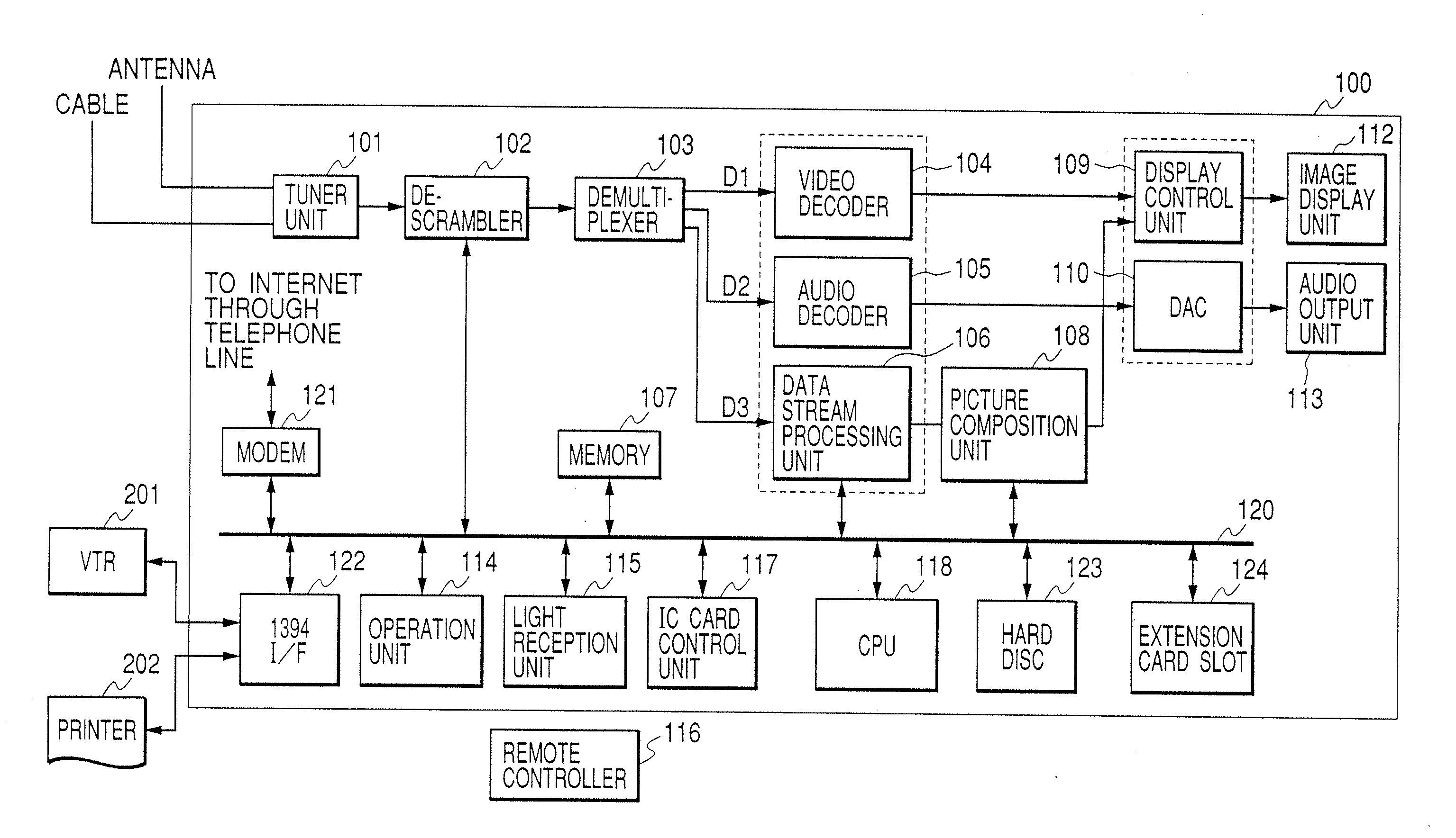
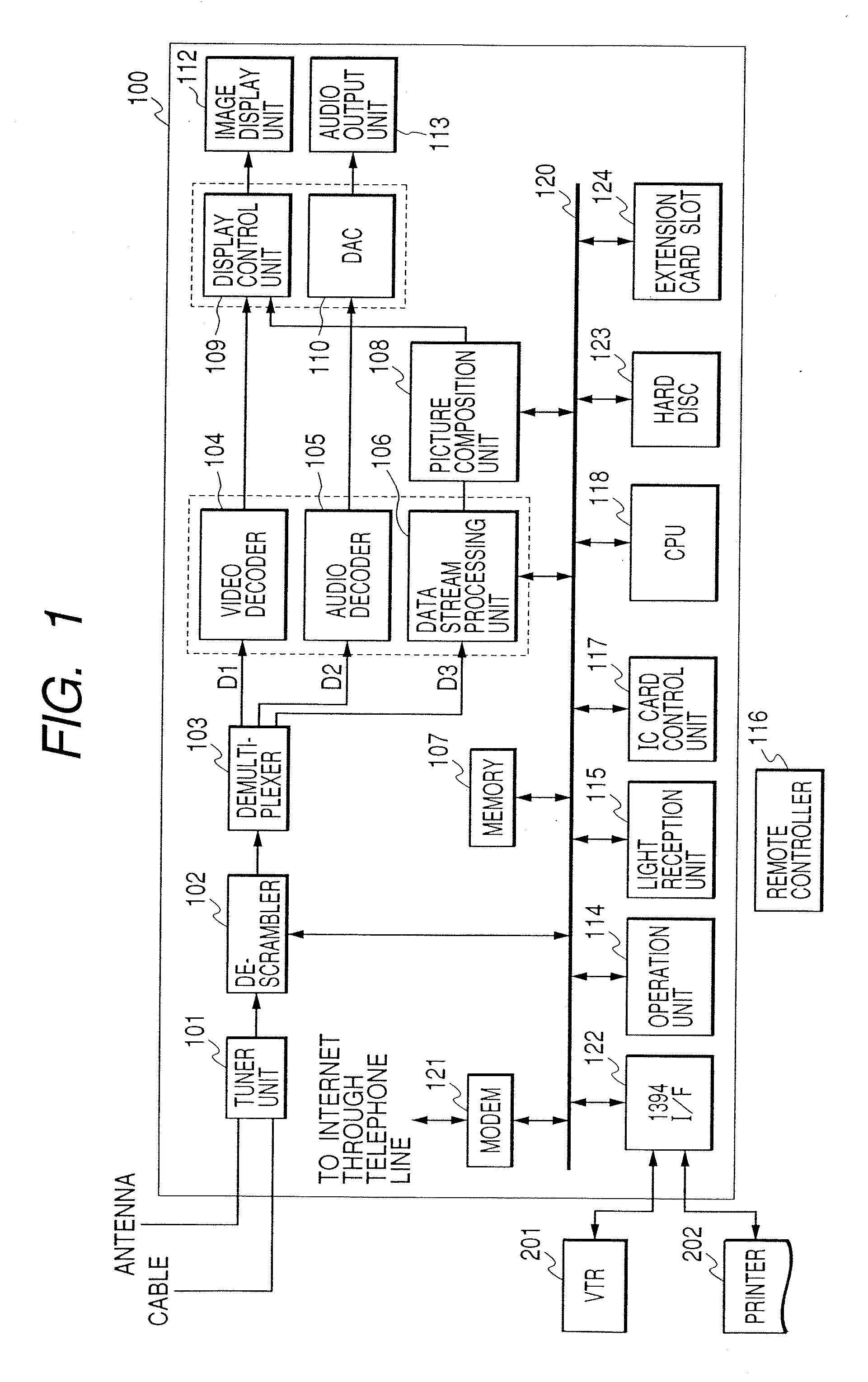
[0036] A first embodiment of the present invention will now be described. FIG. 1 is a diagram showing the configuration of a digital television reception apparatus 100 according to the first embodiment.

[0037] In FIG. 1, a signal received by an antenna (not shown) is transmitted to a tuner unit 101. The tuner unit 101 performs demodulation, error correction and the like on the received signal, and generates digital data having a form called a transport stream. Further, the generated transport stream (TS) data is output to a descrambler 102.

[0038] When the TS data that is scrambled for viewing limitations is received from the tuner unit 101, the descrambler 102 descrambles the TS data based on key information that is included in the TS data for use in the descrambling process, and key information that is output by an IC card control unit 117. The resultant TS data is output to a demultiplexer 103.

[0039] The IC card control unit 117 includes an IC card on which contract information ...


PUM


Abstract

It is the objective of the present invention to easily change between an image display application and the viewing of a program for a digital television, and to improve the usability of the television for operating an image display application. The display change list for a (channel) Up/Down key of a remote controller is dynamically altered so that, during the execution of an image display application, an application screen is displayed by using the Up/Down key. Further, when a memory card is loaded immediately after the television is powered on, a display application can be automatically activated. Furthermore, while a user is watching the television, the contents of a memory card is displayed on a small window in one part of the screen, and execution of the image application controlled by the user. In addition, no icons are displayed while an important program is on displaying. Moreover, since the same color and the same arrangement are used for the four function icons as are used for the four color keys on the remote controller, various processes can be performed for the image application.

Description

BACKGROUND OF THE INVENTION [0001] 1. Field of the Invention [0002] The present invention relates to a function operation technique for a television signal reception apparatus, and in particular to a function operation technique for a television signal reception apparatus having various functions. [0003] 2. Related Background Art [0004] Recently, a broadcast satellite, or communication satellite, system has been put into service that transmits digital television broadcast signals to individual homes. Since this system is capable of providing 100 or more channels, an extensive selection of different types of programs can be provided. Thus, since with this system so many transmittable programs are available, an electric program guide (EPG), which can facilitate the selection of desired programs, is transmitted with other video data and can be displayed on monitoring devices, thereby permitting viewers, by referring to the EPG, to select desired programs. [0005] Because of the developm...

Claims


Application Information

Patent Timeline
IPC IPC(8): H04N7/173H04N5/44H04N7/16H04N5/00H04N5/445H04N5/45H04N7/025H04N7/03H04N7/035H04N21/2665H04N21/418H04N21/422H04N21/431H04N21/462H04N21/47H04N21/472H04N21/478H04N21/4782H04N21/81H04N21/84
CPCH04N1/00424H04N2007/1739H04N1/00453H04N1/00461H04N1/00474H04N5/4401H04N5/44543H04N5/44591H04N5/76H04N5/765H04N5/775H04N5/781H04N5/907H04N7/163H04N9/8042H04N21/2665H04N21/4184H04N21/42204H04N21/4312H04N21/4314H04N21/4622H04N21/47H04N21/472H04N21/478H04N21/4782H04N21/8153H04N21/84H04N2005/4412H04N1/00442H04N21/4221H04N21/426H04N21/4316
Inventor ARATANI, SHUNTAROMORI, SHIGEKIAOYAMA, KEIICHI
Owner CANON KK
Why Eureka
Try Eureka