Fume gun

ume technology, applied in the field of fume extraction devices, can solve the problems of obstructing the operator's vision, visual and respiratory discomfort, and the size and weight of the torch employing such a fume extraction device, and achieve the effect of efficiently drawing ambient air and fumes and cooling the fumes

Active Publication Date: 2006-10-12
LINCOLN GLOBAL INC
View PDF12 Cites 46 Cited by
  • Summary
  • Abstract
  • Description
  • Claims
  • Application Information

AI Technical Summary

Benefits of technology

[0012] Accordingly, it is an aspect of this invention to provide an improved hand held torch in which a smoke and fume extracting nozzle is employed to draw fumes from the area of a welding or cutting operation and in which a fume carrying conduit is formed as an integral part of the torch handle; and to provide an improved torch of the type described wherein the handle of the torch is cooled so that the heat from the welding or cutting operation will not deteriorate the materials used in the gun and will not cause discomfort to the operator.
[0013] Another aspect of the invention is to provide a nozzle for the welding torch which efficiently draws ambient air and fumes into the nozzle and cools the fumes.

Problems solved by technology

During welding or cutting, especially of metallic parts, gases and solid material are generated which not only tend to obstruct the operators vision, but also tend to cause visual and respiratory discomfort.
One difficulty encountered in existing fume extracting torches is in the size and weight of the torch employing such a fume extracting device, and the fact that a large nozzle will interfere with the operator's view.
Another difficulty is in the fact that the fume extracting passageways of existing devices get very hot due to the heat of the fumes drawn away from the weld.
This heat causes the fume carrying conduits to deteriorate, and if these conduits are carried by the gun, then the gun handle becomes hot and uncomfortable to handle.
If the fume extracting conduit is not carried in the handle, then the torch and associated cables and conduits become unwieldy and cumbersome.
Another difficulty, especially where the torch is a welding gun, is in the interference of the fume extracting nozzle with any shielding gas which might be used.
Another problem with existing fume extracting nozzles is that the nozzles are not efficient at extracting ambient air and fumes from the work surface.

Method used


Image

  • Fume gun
  • Fume gun
  • Fume gun

Examples


Embodiment Construction

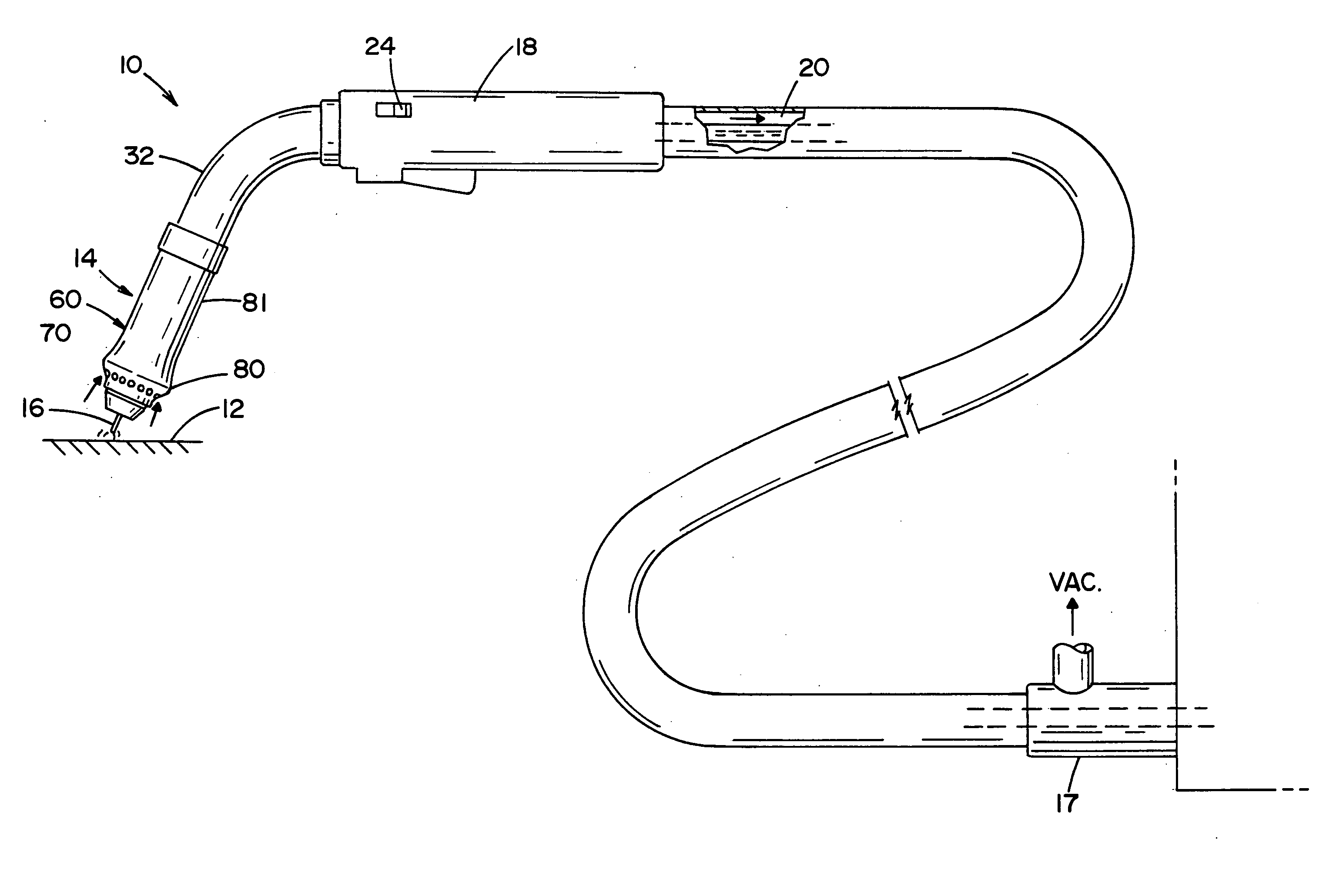
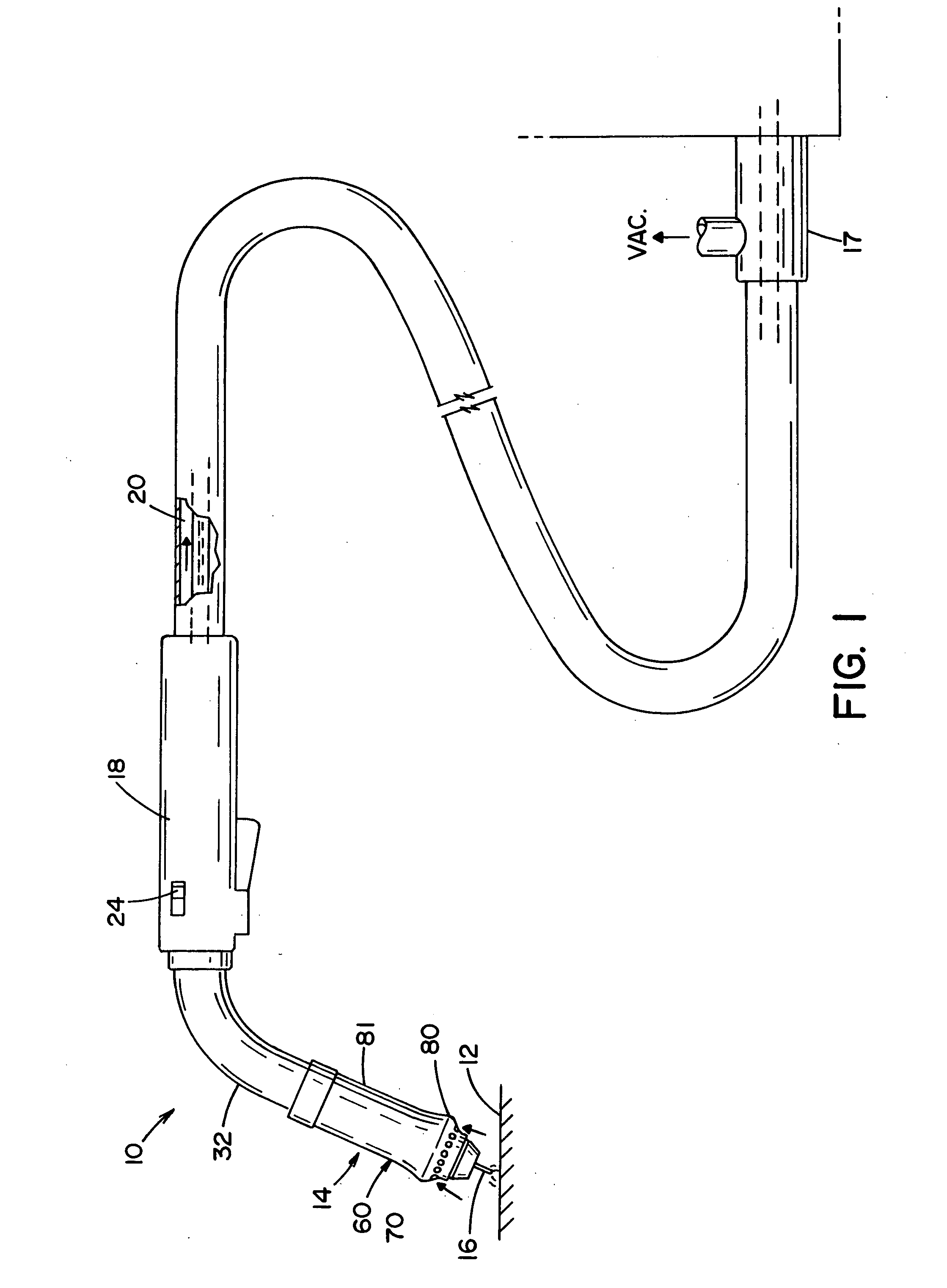
[0021] Reference is now made to the drawings which show the preferred embodiments of the invention, and particularly to FIG. 1 which is a schematic view of a welding system in accordance with a preferred embodiment of the present invention. While the invention will be described herein with reference to gas shielded welding guns or torches, it is to be understood that this invention can also apply to MIG and TIG welding torches as well as to cutting torches.

[0022] Referring to FIG. 1, a welding torch 10 is shown in position above a workpiece 12 which is typically connected by means of a ground wire to a welding power supply (not shown). The welding torch 10 is typically supplied with wire 16 from a wire supply reel via a control system 17. The control system not only regulates the rate at which welding wire 16 moves into the torch, but it can also regulate the flow of shielding gas from a gas source.

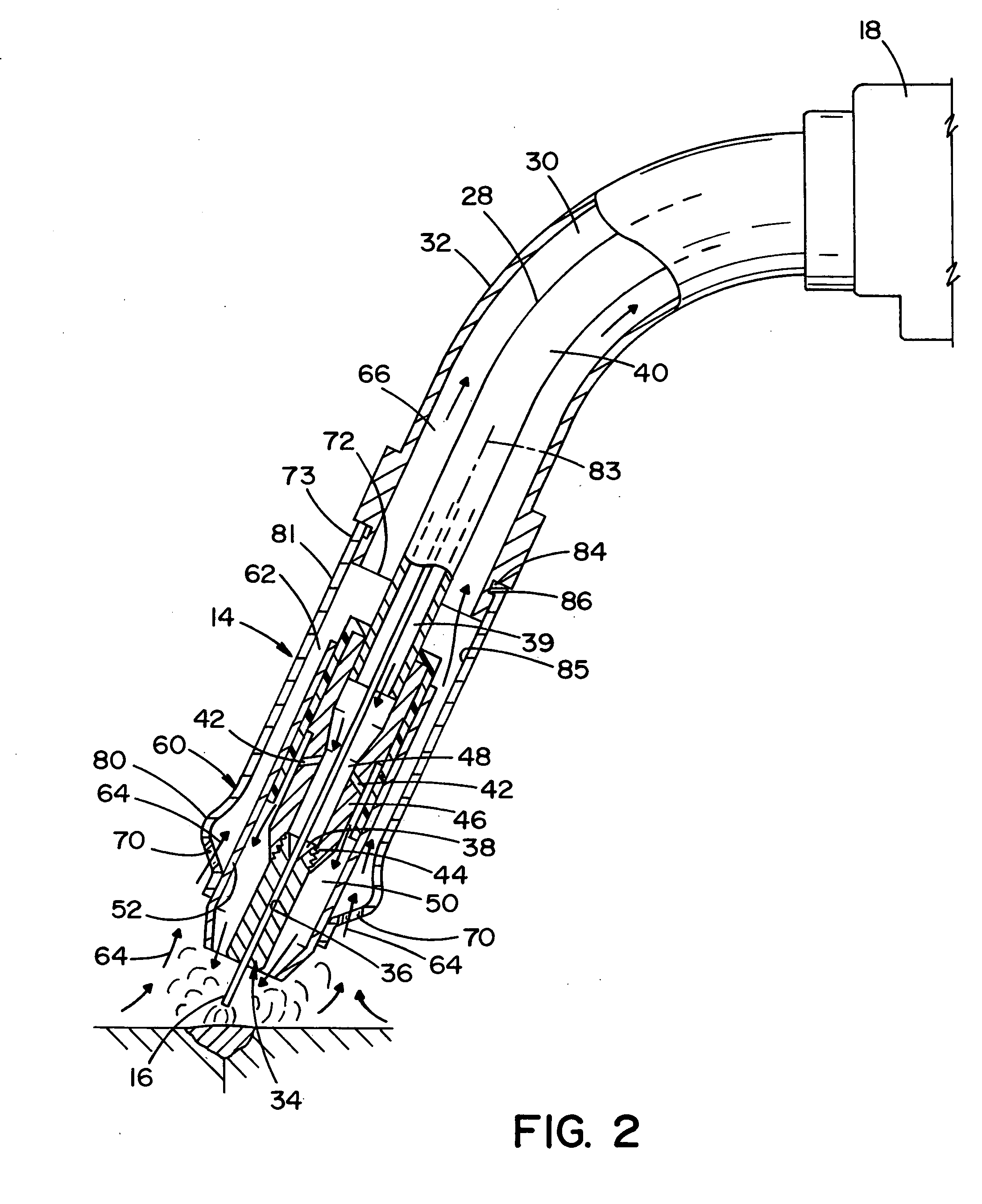
[0023] The welding torch 10 includes a nozzle 14 having a fume extracting orifice c...


PUM

PropertyMeasurementUnit
sizeaaaaaaaaaa
flow rateaaaaaaaaaa
inner diameteraaaaaaaaaa

Abstract

A torch for use in welding operations during which smoke and/or fumes are created has a nozzle and a handle connected to a conduit extending between the handle and the nozzle. A fume extraction duct extends from the nozzle and through the handle. An annular member surrounds the axial end of the nozzle and has a plurality of openings oriented such that fumes and ambient air are extracted in a direction substantially parallel to the longitudinal axis of the nozzle. A switch is provided to control fume extraction between a full flow rate and a partial flow rate.

Description

BACKGROUND [0001] During welding or cutting, especially of metallic parts, gases and solid material are generated which not only tend to obstruct the operators vision, but also tend to cause visual and respiratory discomfort. This is especially true when welding or cutting in confined areas, such as assembly lines in factories, where several such operations may be in progress simultaneously. [0002] One difficulty encountered in existing fume extracting torches is in the size and weight of the torch employing such a fume extracting device, and the fact that a large nozzle will interfere with the operator's view. An example of a previous attempt to incorporate a fume extracting device with a hand held welding torch is found in U.S. Pat. No. 3,980,860 which is hereby incorporated by reference. [0003] Another difficulty is in the fact that the fume extracting passageways of existing devices get very hot due to the heat of the fumes drawn away from the weld. This heat causes the fume car...

Claims


Application Information

Patent Timeline
Patent Type & Authority Applications(United States)
IPC IPC(8): B23K9/173
CPCB23K9/325B08B15/04
Inventor ZAMUNER, FRANK
Owner LINCOLN GLOBAL INC
Why Eureka
Try Eureka