Bag type squeeze bottle

a squeeze bottle and bag-type technology, applied in the field of bag-type squeeze bottles, can solve the problems of reducing the service life of the bottle, so as to improve the service life and eliminate waste. , the effect of enhancing the performance of the bottl

Inactive Publication Date: 2006-10-12
FUN DAMENTAL TOO
View PDF9 Cites 67 Cited by
  • Summary
  • Abstract
  • Description
  • Claims
  • Application Information

AI Technical Summary

Benefits of technology

[0008] This capability is provided by a combination of bottle valving and bag materials together with structural dimensions that are mutually compatible. A dispensing nozzle is employed which is not only substantially liquid-tight but also airtight. This prevents air from escaping back into the bag when pressure on the outside of the squeeze bottle is released. The tendency for re-admitting air into the bag is also mitigated by the use of an efficient umbrella type one-way bottle air valve with a high flow rate. These structures are utilized in combination with a highly resilient bottle that quickly snaps back to its normal shape when squeezing pressure is released. This allows the interior of the bottle to be recharged with air quickly and without producing any adverse effects on the product bag that would increase its tendency for drawing air back through the nozzle and into the bag.
[0009] The invention also uses an inversion collar to hold the bag at its midpoint so that the bag folds inwardly upon itself and up into the collar as liquid product is expelled. This enhances the performance of the bottle and prevents product from being trapped between irregular folds in the bag as it is compressed by the internal air pressure of the bo...

Problems solved by technology

Furthermore, without proper valving which maintains the internal bottle air pressure, the more liquid products tend to fall to the bottom of the bag leaving an air space at the top of the bag which must be expelled each time before the liquid is discharged.
This adversely affects the performance of the dispenser.
A general problem with bag-in-bottle type squeeze dispensers of the prior art is that the discharge of dispensed product is less than complete, creating waste.
This occurs because the ...

Method used


Image

  • Bag type squeeze bottle
  • Bag type squeeze bottle
  • Bag type squeeze bottle

Examples


Embodiment Construction

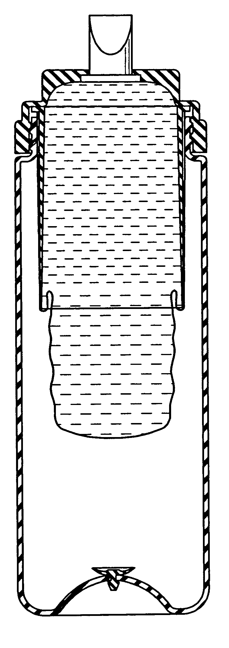
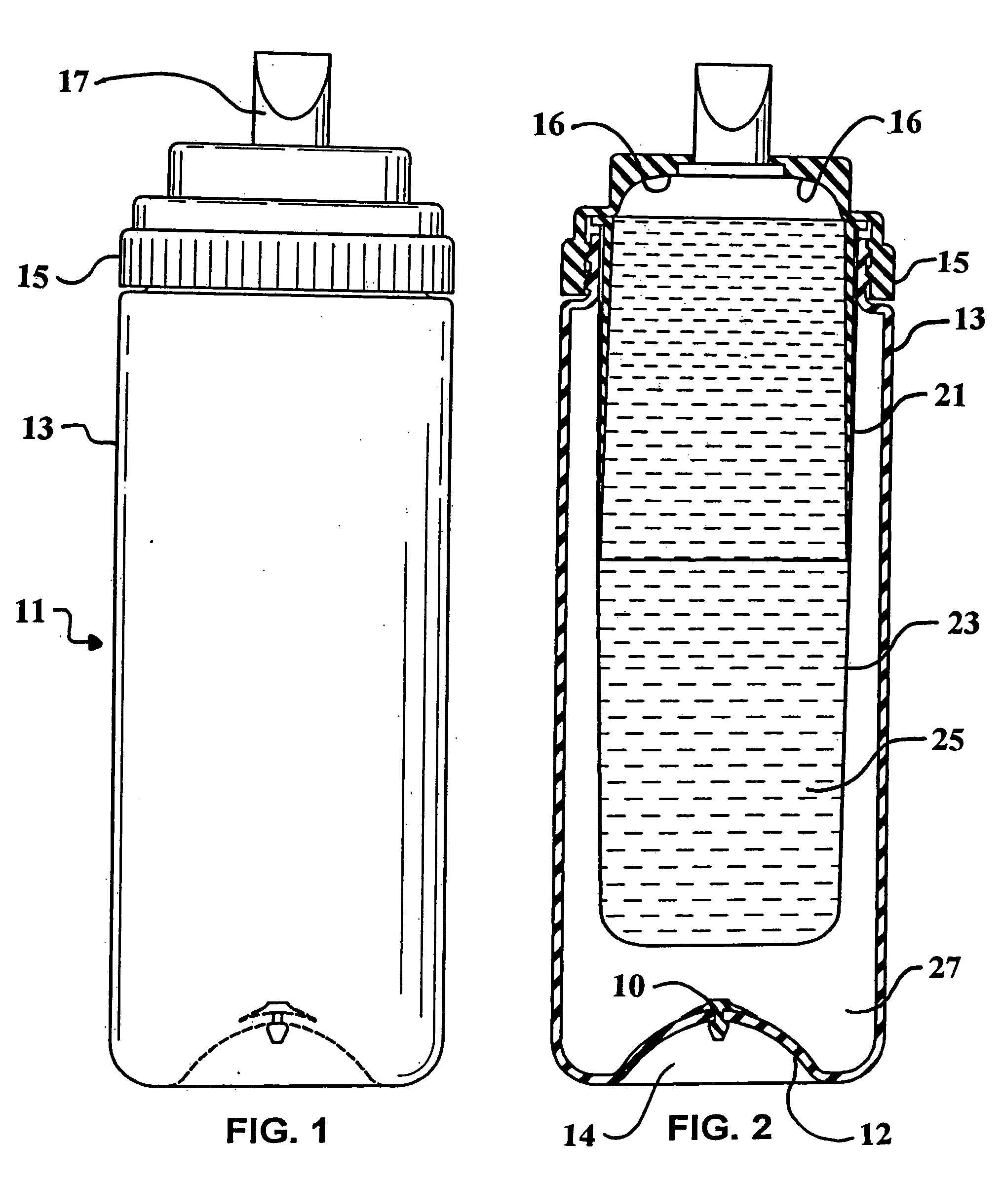
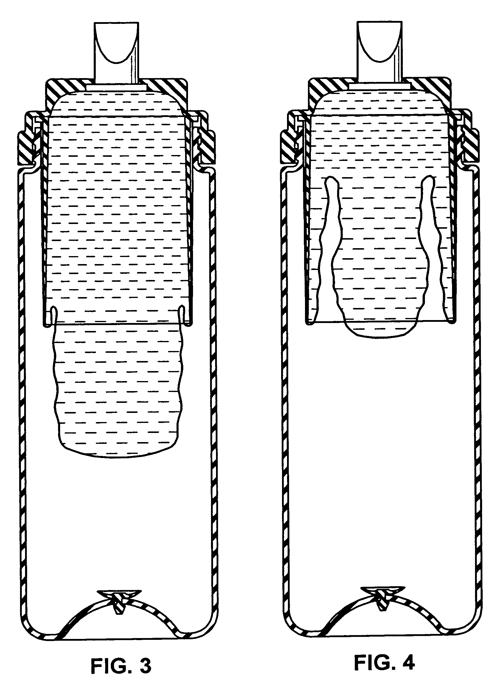
[0016] Referring now to FIG. 1, the squeeze bottle 11 of the invention generally includes a flexible outer wall which is highly resilient and dimensioned to fit comfortably within the consumer's hand for squeezing. At the top of the bottle is a removable threaded cap which carries a duckbill type dispensing nozzle 17. This duckbill nozzle known in the art includes opposing leaflets which are resiliently biased toward each other. The duckbill valve of the present invention is selected to include leaflets which are of sufficient surface area and closing force so that the valve provides both a liquid and airtight seal between the interior of the bottle and the surrounding environment. The bottom wall 12 of the bottle 11 includes a concavity 14 with an umbrella type air valve 10. This valve provides the one-way admission of air into the bottle caused by negative air pressure within which occurs when the squeezing pressure on the outside of the bottle is released and the expanding sidewa...


PUM


Abstract

A high performance squeeze bottle dispenser includes an internal product-containing bag which is in fluid communication with a dispensing nozzle. The dispensing nozzle is airtight to prevent air from escaping back into the bag when pressurization of the bottle is released. A one-way air valve in a wall of the bottle admits air into the interior of the bottle around the outside of the product bag to provide a pumping action which pressurizes the interior of the bottle to cause product expulsion through the nozzle. An inversion collar projects into the bag so that the bag folds inwardly upon itself and up into the collar as product is expelled. The collar may also include an upper inside dome-shaped surface which matches the shape of the inside of the bottom of the bag to achieve near-complete expulsion of product to reduce waste.

Description

FIELD OF THE INVENTION [0001] The present invention relates to a bag-in-bottle type squeeze bottle having an inner receptacle incorporating a flexible bag for containing and dispensing various types of fluid products. More specifically, it pertains to flexible bag dispensers that include product bags which invert as they empty. BACKGROUND OF THE INVENTION [0002] Squeeze type bottle dispensers are well known for use in packaging and dispensing various types of liquid products including those which are more viscous such as toothpaste. In order to improve the product expulsion of viscous materials, bag-in-bottle type dispensers have been employed because the more viscous products are difficult to expel from regular dispensers. Some dispensers include internal means for inverting the bag in upon itself to enhance their performance. Another general type is a pump dispenser which utilizes a piston pump to create the internal air pressure necessary to dispense the product. Since the pressu...

Claims


Application Information

Patent Timeline
IPC IPC(8): B65D35/28B65D37/00
CPCB65D83/0055
Inventor STERNBERG, HARRY W.
Owner FUN DAMENTAL TOO
Why Eureka
Try Eureka