Offset disc hammer assembly for a hammermill

a technology of offset disc and hammer, which is applied in the field of hammermills, can solve the problems of reducing the efficiency of the assembly, and limiting the use of assembly length in the shredding process, so as to reduce the number of parts and reduce the amount of space available. , the effect of more efficient shredding process

Inactive Publication Date: 2006-10-12
RIVERSIDE ENG
View PDF16 Cites 9 Cited by
  • Summary
  • Abstract
  • Description
  • Claims
  • Application Information

AI Technical Summary

Benefits of technology

[0006] The present invention has several advantages over existing hammer assemblies for hammermills. Most significantly, the offset disc arrangement allows hammers to be placed across the entire length of the assembly, instead of being spaced apart by the width of the discs. The ability to use the entire length of the assembly creates a more efficient shredding process. In addition, the use of an offset disc assembly instead of a spider assembly or a combination spider-disc assembly reduces the number of parts that need to be assembled, as well as the amount of space available for unshredded materials to become lodged in the assembly. Various other features, objects, and advantages of the invention will be made apparent to those skilled in the art from the accompanying drawings and detailed description thereof.

Problems solved by technology

Although existing disc assemblies, spider assemblies, and combination disc-spider assemblies have certain benefits and advantages, existing assemblies also have limitations.
One limitation associated with existing disc assemblies is that much of the length of the assembly is not used in the shredding process because the hammers cannot be mounted in the same circumferential space as the discs.
One limitation of existing spider assemblies is that the spider arms create inlets in which unshredded materials can become lodged, decreasing the efficiency of the assembly.
Likewise, a combination disc-spider assembly does not allow hammers to be mounted in the same circumferential space as the discs, and can also allow unshredded material to become lodged in the inlets created by the spider arms.

Method used


Image

  • Offset disc hammer assembly for a hammermill
  • Offset disc hammer assembly for a hammermill
  • Offset disc hammer assembly for a hammermill

Examples


Embodiment Construction

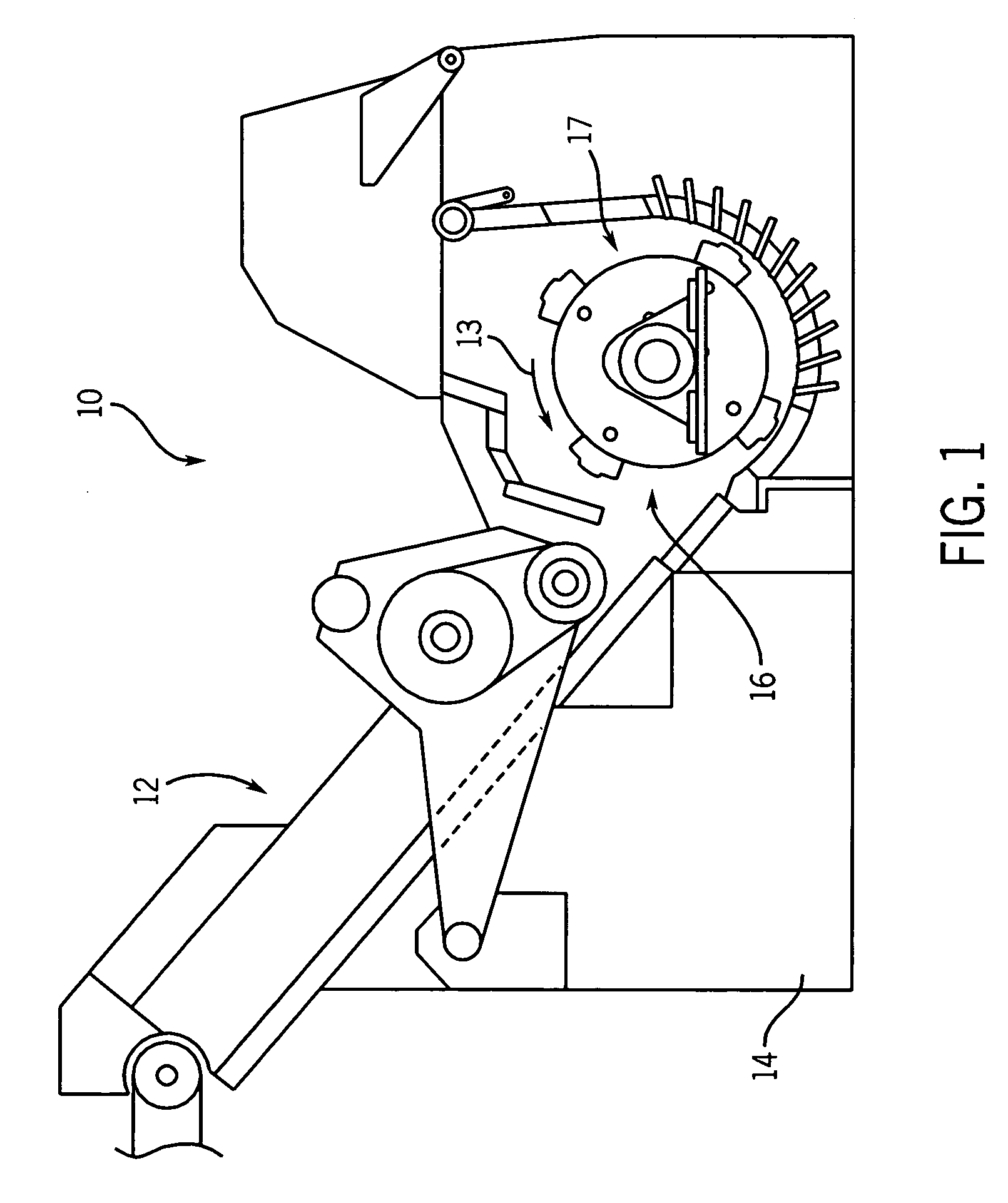
[0012] The present invention is an offset disc hammer assembly for use in a hammermill for shredding scrap materials such as automobiles. FIG. 1 shows one embodiment of a hammermill 10 including a hammer assembly 17 according to one embodiment of the present invention. The hammermill 10 has a feed conveyor 12 that delivers materials to be shredded into hammermill housing 14. The housing 14 includes a shredding chamber 16, wherein a hammer assembly 17 is mounted for rotary motion.

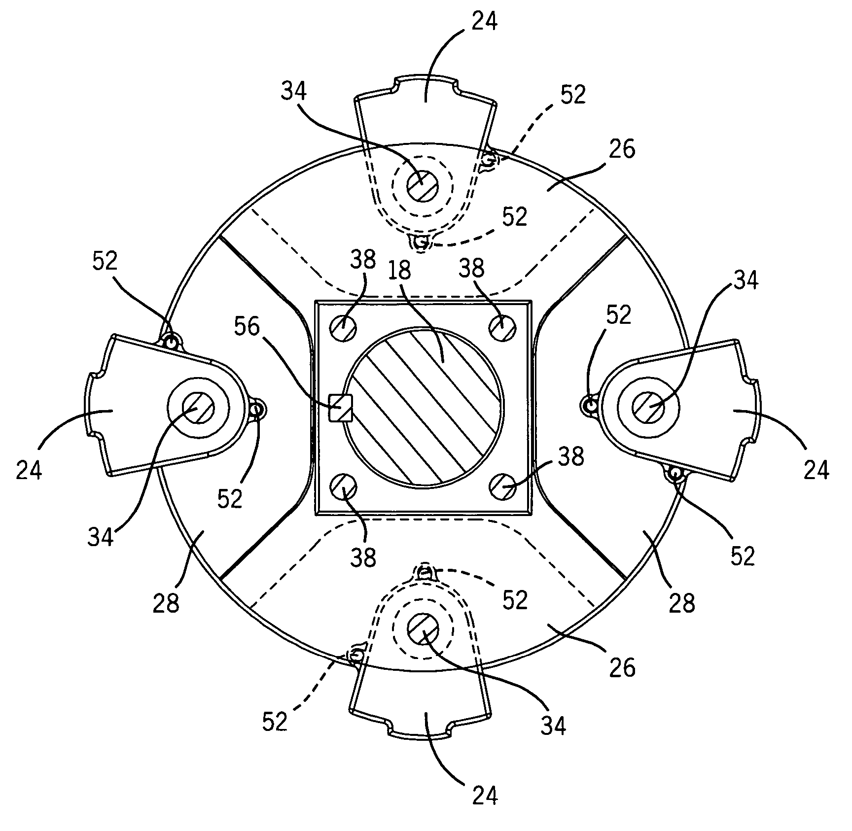
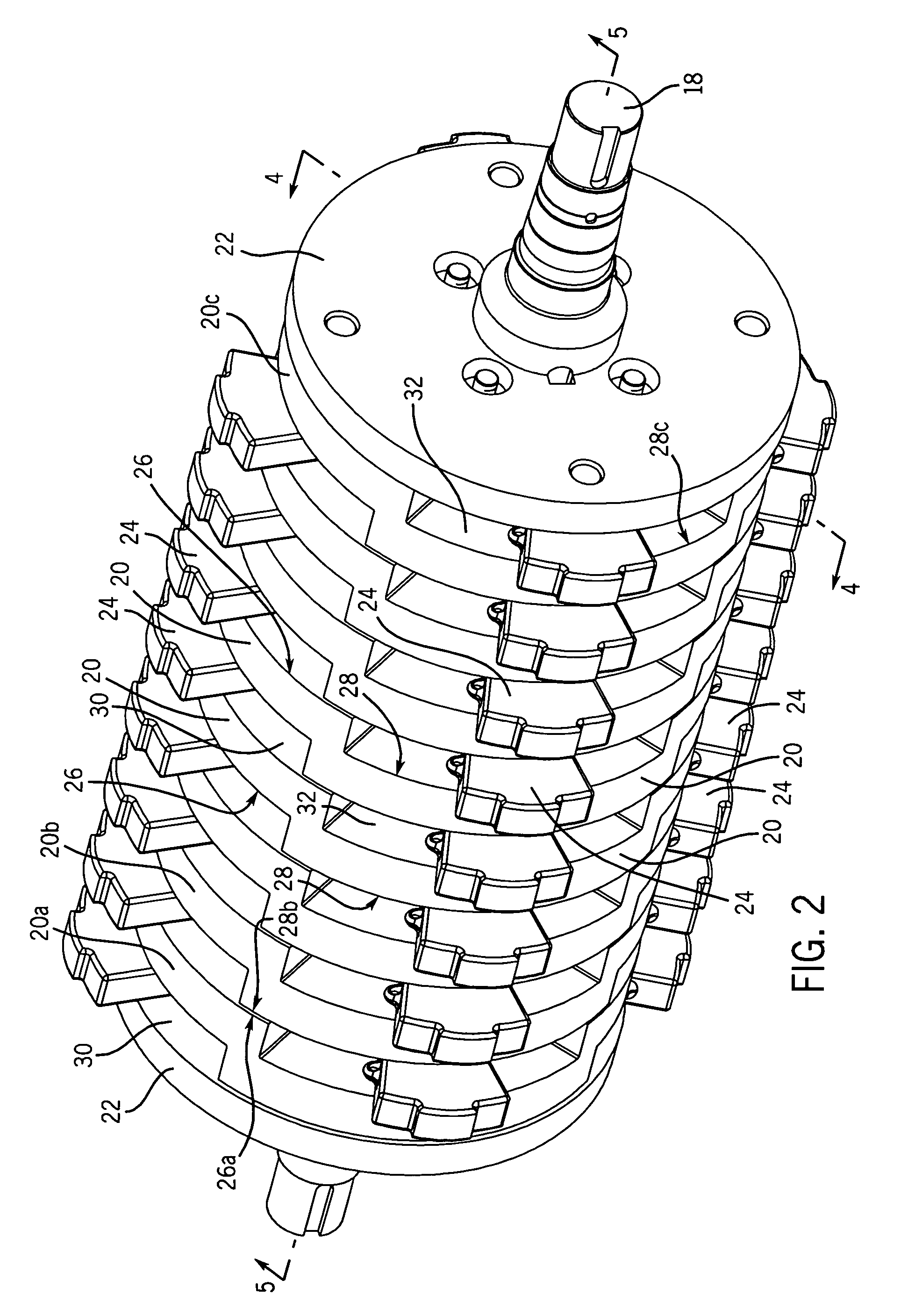
[0013]FIGS. 2-5 illustrate one embodiment of an offset disc hammer assembly in accordance with the present invention. For clarity of illustration given the repetitive nature of the assembly, representative parts, as opposed to each of the parts, associated with a particular reference number are labeled in FIGS. 2-5. The hammer assembly 17 includes a shaft 18, a plurality of offset discs 20 arranged in axial alignment along the length of the shaft 18, and a plurality of hammers 24. End discs 22 are also arra...


PUM


Abstract

A hammer assembly for a hammermill is disclosed. The hammer assembly includes a drive shaft, a plurality of offset discs arranged in axial alignment about the drive shaft, and a plurality of hammers. Each offset disc is placed along the drive shaft adjacent to at least one other offset disc. The arrangement of the discs defines a plurality of alternately offset mounting spaces such that a hammer may be mounted in the offset mounting spaces.

Description

FIELD OF THE INVENTION [0001] The present invention relates generally to hammermills for shredding scrap materials, and more particularly to an offset disc hammer assembly for a hammermill. BACKGROUND OF THE INVENTION [0002] Hammermills for shredding scrap materials such as automobiles are also known as fragmentation machines, and shred or fragment the scrap materials using a hammer assembly including a rotor assembly with a plurality of impact devices such as hammers mounted thereon. The hammer assembly is typically driven by a 2,000-10,000 horsepower (HP) motor at 450-720 revolutions per minute (rpm). Two common hammer assembly configurations in use today include disc assemblies and spider assemblies. The disc assembly generally includes a plurality of discs arranged in spaced-relation about a drive shaft with a plurality of hammers mounted in between the discs. Spacers are typically used in between each disc to create a mounting space for the hammers. One example of a disc assemb...

Claims


Application Information

Patent Timeline
Patent Type & Authority Applications(United States)
IPC IPC(8): B02C13/00
CPCB02C13/04B02C2013/2808B02C13/28
Inventor STELK, JOHN C.
Owner RIVERSIDE ENG
Why Eureka
Try Eureka