Relaying piston multiuse valve-less electromagnetically controlled energy conversion devices

Inactive Publication Date: 2006-10-12
PAL ANADISH KUMAR
View PDF4 Cites 14 Cited by
  • Summary
  • Abstract
  • Description
  • Claims
  • Application Information

AI Technical Summary

Benefits of technology

[0025] 6. Full and uniform sweep through the hollow toroidal cylinder of all the pistons, insures full scavenging of exhaust gases and uniform wear of the cylinder inner surface.
[0029] Accordingly, a principle object of the present invention is to devise an easily reversible, energy conversion electromagnetically controlled apparatus to convert chemical energy produced from combustion of gases or hydrocarbons into kinetic energy in rotational form for further conversion into mechanical work or electricity.

Problems solved by technology

It can only handle clean pumping media.

Method used


Image

  • Relaying piston multiuse valve-less electromagnetically controlled energy conversion devices
  • Relaying piston multiuse valve-less electromagnetically controlled energy conversion devices
  • Relaying piston multiuse valve-less electromagnetically controlled energy conversion devices

Examples


Embodiment Construction

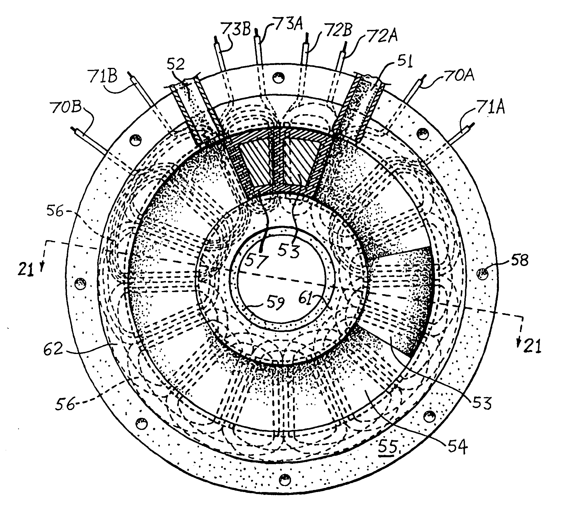
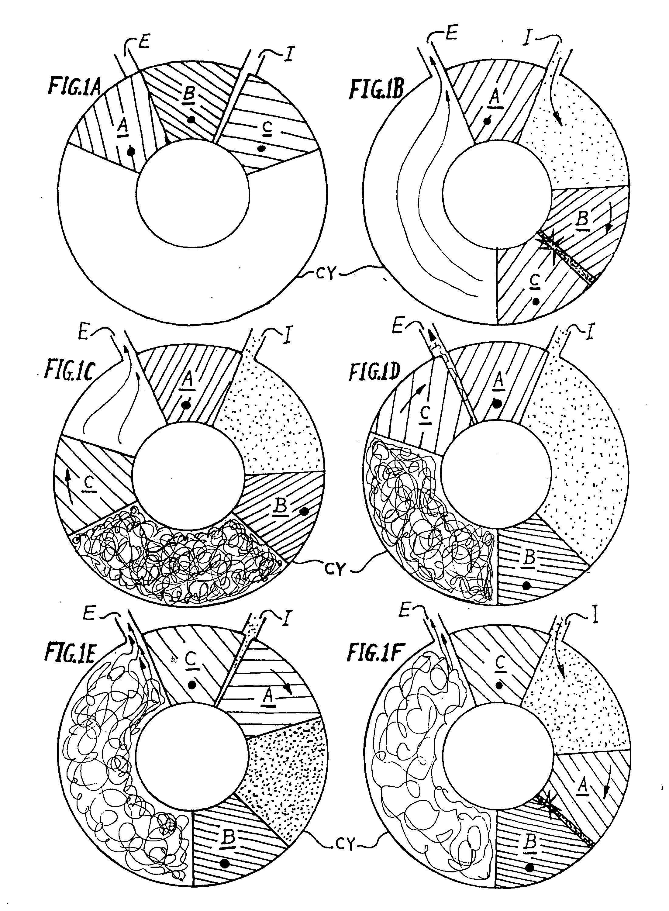
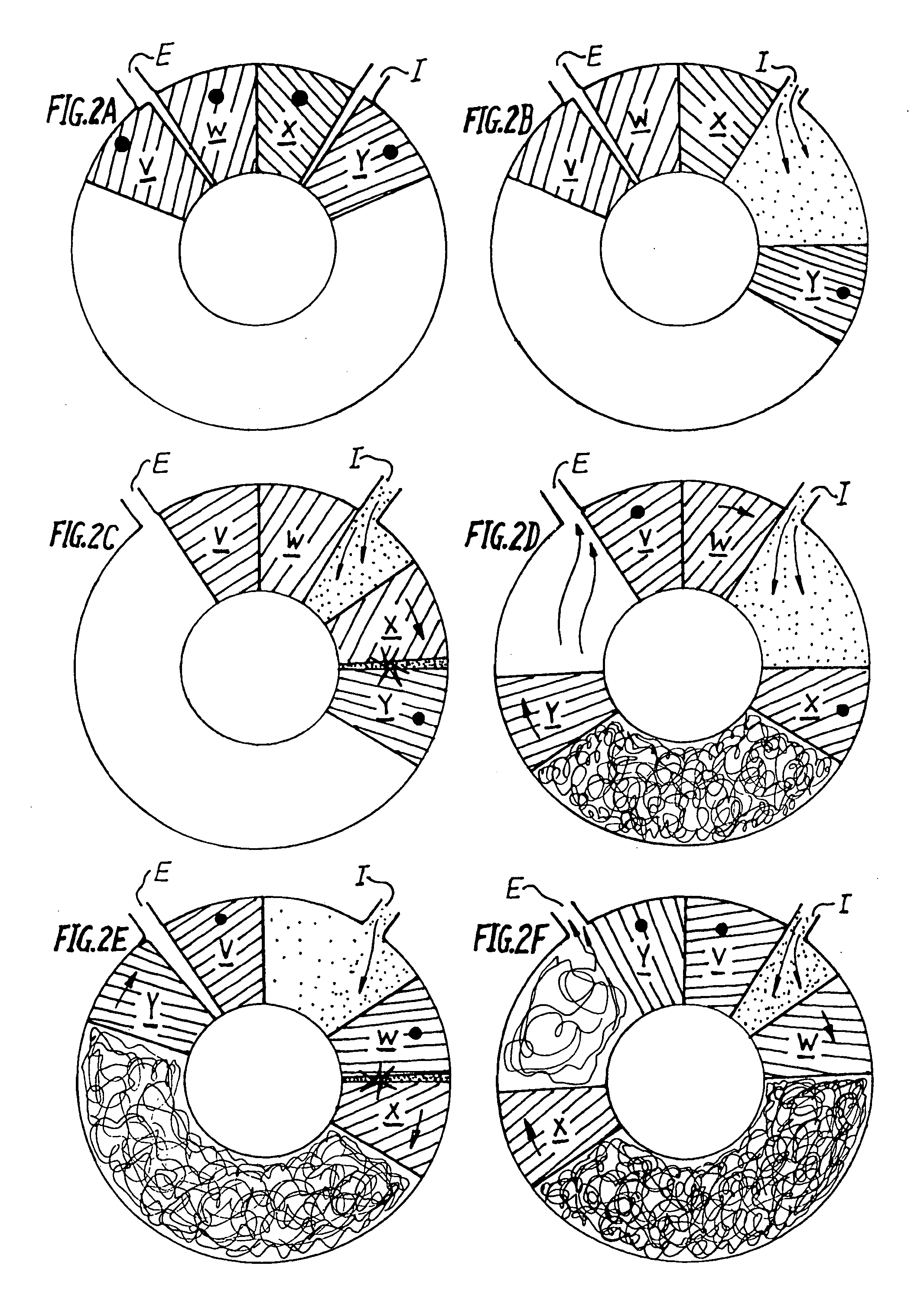
[0067]FIG. 1A through FIG. 1F show the workings of the internal-combustion engine of the present invention with three pistons. Pistons marked A, B and C, are fully identical and have ferromagnetic properties. They are denoted separately as A, B and C to explain properly their working interrelations in the engine. Pistons A, B and C are slidably fitted inside hollow toroidal cylinder CY. There are two angularly spaced ports I and E, positioned on the outermost circumferential periphery of CY. Here I functions as the intake port, and E is the exhaust port. The clearances between the inside surface profile of hollow toroidal cylinder CY and the outer semi-toroidal profile of pistons A, B and C are such as to effect sufficient volumetric compression of combustible gases to lead to triggered or spontaneous combustion inside hollow toroidal cylinder CY, and yet to allow smooth sliding movement of pistons A, B and C in the presence of adequate lubrication.

[0068]FIG. 1A shows the preferabl...


PUM


Abstract

Energy conversion devices employing gases and / or liquids as medium, constructed with a hollow, preferably toroidal cylinder having two ports and two, or more, identical ferromagnetic pistons moveably sealing the hollow cylinder. Movements of the pistons are electromagnetically selectable from the outside of the cylinder to either impart varying unidirectional forces on the medium and / or to influence a magnetic circuit placed outside the cylinder for the generation of motive or electromotive forces. In a pump, a compressor and an externally heated engine, the selective movement of the pistons always maintains a piston between the two ports. In an internal-combustion engine, addition is made of more pistons and one piston is selectively stopped and approached by the adjacent piston, compressing a gaseous mixture to effect combustion; electronic detection of the combustion allows the rapid electromagnetic release of the stopped piston and stops the adjacent piston which was compressing prior to the combustion.

Description

BACKGROUND OF THE INVENTION [0001] This invention in its various forms is directed to the field of pumps, engines and electrical generators. This invention can be implemented for making of various kinds of engines, namely, Stirling, external combustion, internal combustion, and free-piston engines. This invention can also be implemented in electrically driven pumps and compressors. [0002] At present the most common engine is an internal-combustion engine. Research is being done in the field of free-piston engines (U.S. Pat. No. 6,199,519). Current free-piston engines are reciprocating type with a linear alternator integrated with the piston or pistons. Linear alternators are heavier than their rotary counterparts. Scavenging of the burnt fuel is also a problem. Additional mechanical or electromagnetically operated valves have to be used in order to obtain sure scavenging and intake in free-piston linear alternators. Linear free-piston engines are unable to produce mechanical energy ...

Claims


Application Information

Patent Timeline
IPC IPC(8): H02K19/00H02K1/00H02K1/12
CPCH02K7/1884
Inventor PAL, ANADISH KUMAR
Owner PAL ANADISH KUMAR
Why Eureka
Try Eureka