Circuit for generating a reference current

a reference current and circuit technology, applied in the direction of electrical variable regulation, process and machine control, instruments, etc., can solve the problems of resistance and maximum frequency contraindication, worst-case constraints for resistance and maximum frequency, and assembly failure to compensate for tolerances (on the order of 20%), so as to avoid overconsumption

Inactive Publication Date: 2006-10-12
STMICROELECTRONICS SRL
View PDF18 Cites 13 Cited by
  • Summary
  • Abstract
  • Description
  • Claims
  • Application Information

AI Technical Summary

Benefits of technology

[0024] The present invention also aims at avoiding the overconsumption due to the manufacturing tolerances of the resistor of a reference current generation circuit.

Problems solved by technology

A disadvantage of the circuit of FIG. 3 is that the integration of resistor R30, most often in the form of a polysilicon resistor, makes it necessary to take into account its manufacturing tolerances in the transistor sizing to take the worst case into account.
Indeed, such tolerances (on the order of 20%) are not compensated for by the assembly.
Another disadvantage of the circuit of FIG. 3 is that the worst case must also be taken into account for the operating frequencies of the amplifiers (10, FIG. 2) biased by the assembly.
Further, the worst-case constraints for the resistance and the maximum frequency are contrary.
Such sizings taking into account the worst cases result in high losses in most applications, the excess bias current of the amplifiers being dissipated in the transistors of their respective branches.

Method used


Image

  • Circuit for generating a reference current
  • Circuit for generating a reference current
  • Circuit for generating a reference current

Examples


first embodiment

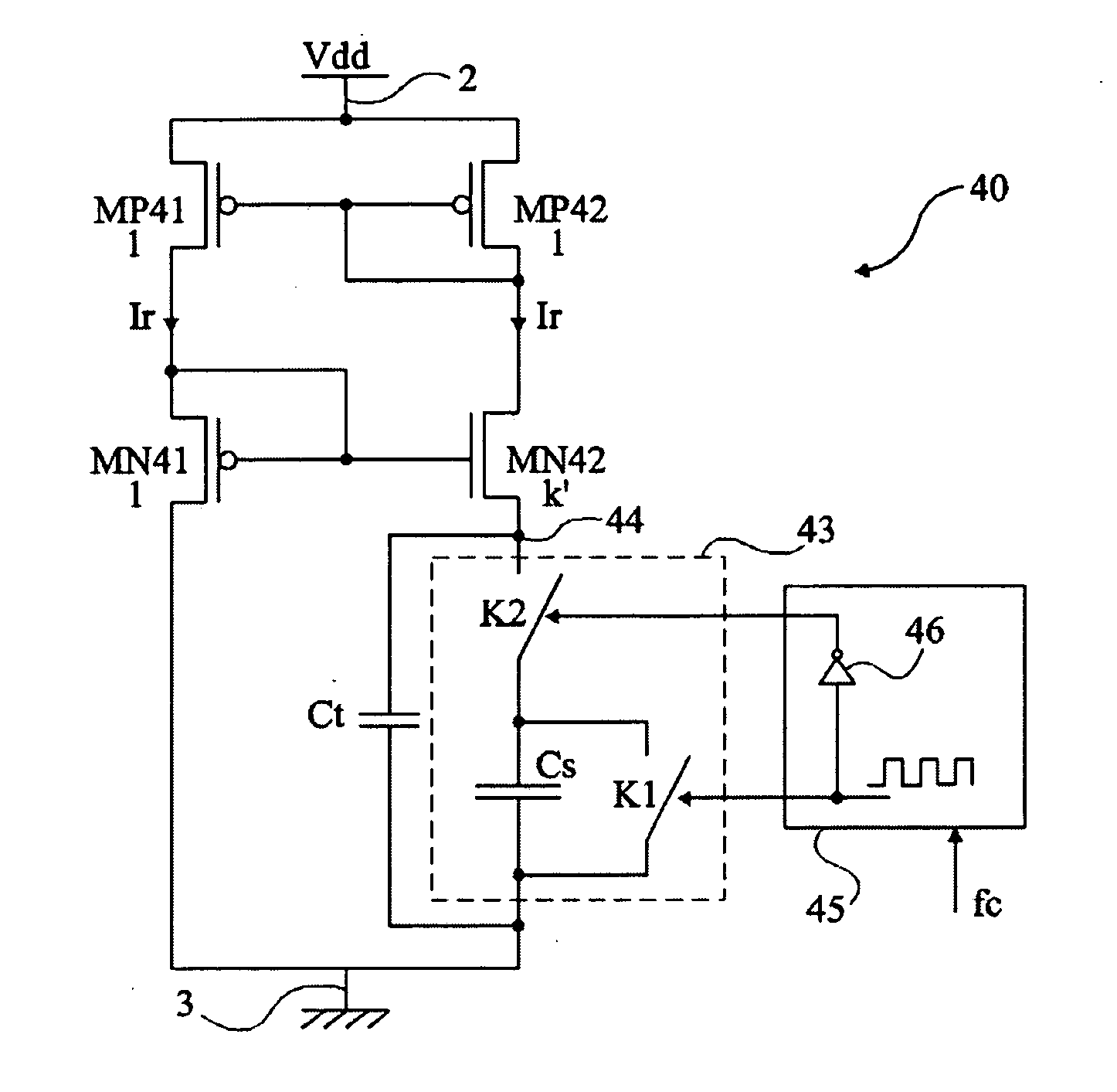
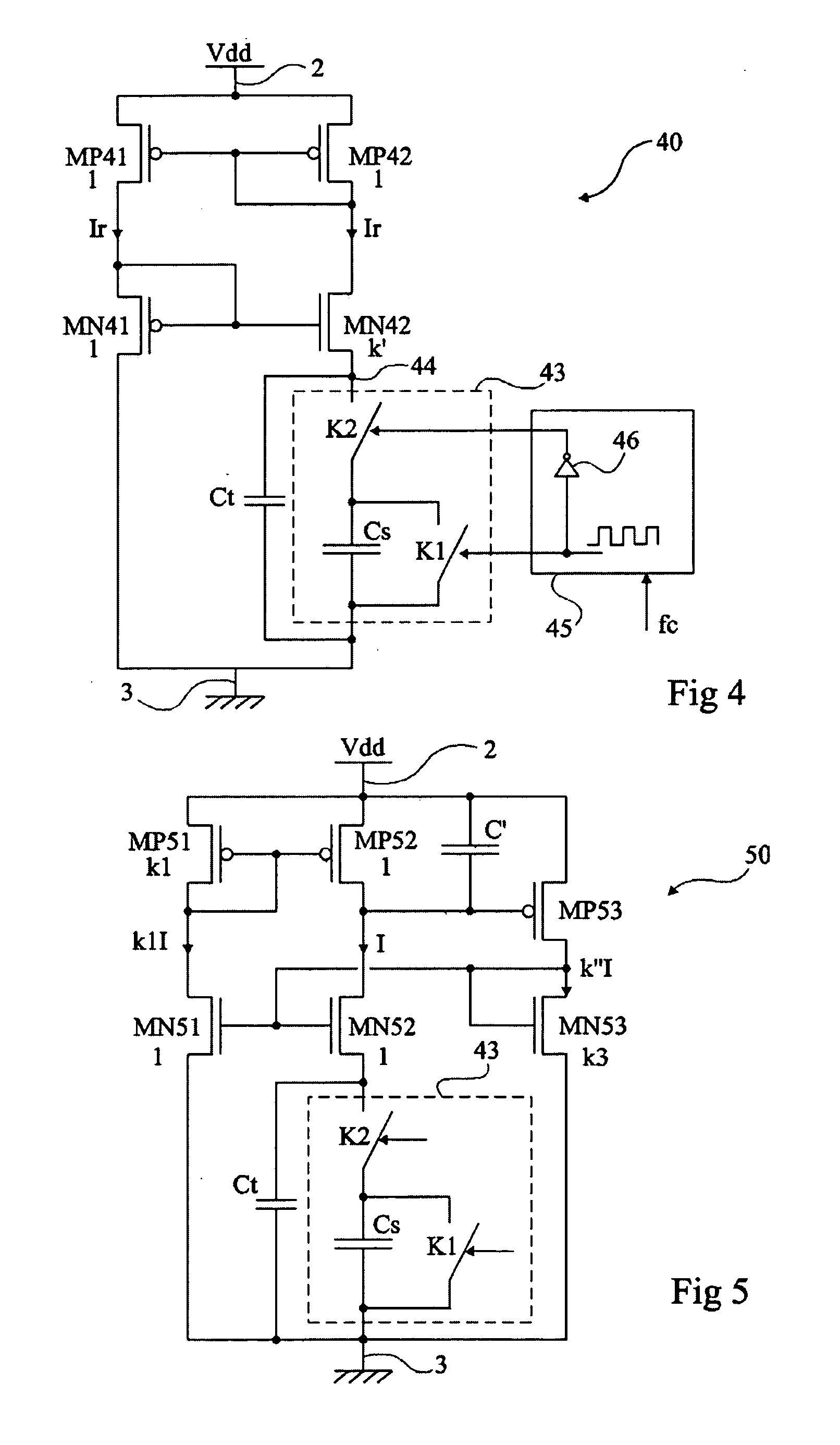
[0047]FIG. 4 shows a reference current generation circuit 40 according to the present invention.

[0048] Circuit 40 generates a current Ir intended to be copied by current mirror assemblies to bias, for example, differential stages of transconductance amplifiers of the type described in relation with FIG. 2. The present invention will be described in relation with such an example of amplifier but it should be noted that it more generally applies to the generation of a reference current and that the application for biasing any amplifier, operational or not, differential or not, etc. is a preferred application.

[0049] Circuit 40 comprises two parallel branches between two terminals 2 and 3 of application of a D.C. supply voltage Vdd. A first branch comprises two MOS transistors, respectively with a P channel MP41 and with an N channel MN41, in series between terminals 2 and 3. According to this embodiment of the present invention, a second branch comprises two MOS transistors, respectiv...


PUM


Abstract

A circuit for generating a reference current, including, between two terminals of application of a supply voltage: at least a first branch formed of at least a first and of at least a second transistors in series; at least a second branch formed of at least a third and of at least a fourth transistors in series with a switched-capacitance circuit.

Description

BACKGROUND OF THE INVENTION [0001] 1. Field of the Invention [0002] The present invention generally relates to electronic circuits and, more specifically, to the generation of reference currents for biasing means, intended for amplifiers. [0003] The present invention applies, for example, to analog-to-digital converters and to the generation of currents for biasing the differential stages of the operational amplifiers of the converter. The present invention also applies to active filters. More generally, the present invention applies to any reference current generator. [0004] 2. Discussion of the Related Art [0005]FIG. 1 schematically shows in the form of blocks an analog-to-digital converter 1 (ADC) of the type to which the present invention applies. Such a converter is supplied by a D.C. voltage Vdd applied between two terminals 2 and 3 of circuit 1. In the example of FIG. 1, converter 1 has differential inputs. A differential signal Vin is applied between two input terminals 4 an...

Claims


Application Information

Patent Timeline
Patent Type & Authority Applications(United States)
IPC IPC(8): G05F1/10
CPCG05F3/262
Inventor MORO, JEAN-LUCRAMET, SERGESABUT, MARC
Owner STMICROELECTRONICS SRL
Why Eureka
Try Eureka