LED assembly with a communication protocol for LED light engines

a technology of led light engine and communication protocol, which is applied in the direction of audible advertising, identification means, advertising, etc., can solve the problems of small input energy transfer, most of the input energy of traditional lighting is wasted, and the incandescent bulb is a traditional incandescent bulb

Inactive Publication Date: 2006-10-12
DIALIGHT CORP
View PDF5 Cites 61 Cited by
  • Summary
  • Abstract
  • Description
  • Claims
  • Application Information

AI Technical Summary

Benefits of technology

[0021] Accordingly, one object of the present invention is to provide a novel LED assembly and novel method of m...

Problems solved by technology

Although inexpensive to manufacture, the traditional incandescent bulb suffers from two disadvantages.
First, most of the input energy of traditional lighting is wasted as heat or infrared (non-visible) light; only a small amount of the input energy is transferred to visible light.
Second, the lifetime of the incandescent bulb is limited and when failure occurs it is catastrophic.
Halogen light sources are a slight improvement in efficiency and lifetime over incandescent light sources for a marginal increase in cost.
The filtering process takes white lighting and removes all the light except the required light of the specified color and therefore further reduces the efficiency of the light source.
Traditional lighting also is broadcast in all directions from the source, which may not be advantageous when the goal is to illuminate a small object.
Lastly, traditional lighting has a non-linear relationship between brightness and input current.
This non-linearity makes it difficult to dim the light source easily.
Generally, an individual LED produces a low level of light output that is insufficient for...

Method used


Image

  • LED assembly with a communication protocol for LED light engines
  • LED assembly with a communication protocol for LED light engines
  • LED assembly with a communication protocol for LED light engines

Examples


first embodiment

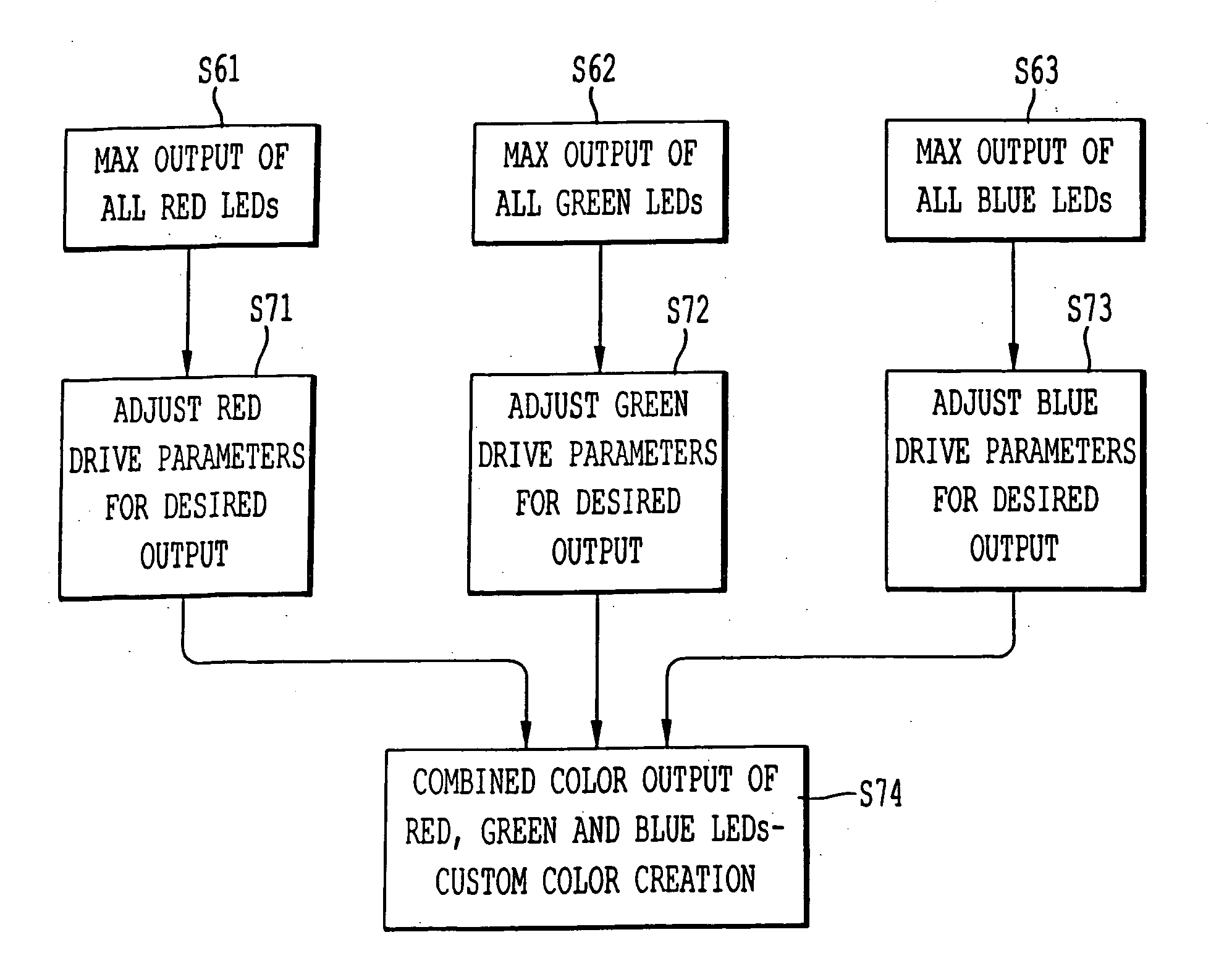
[0066] the overall control operation of the LED assembly 100 of the present invention as shown in FIG. 6a is to utilize the stored baseline light output data of the Red LEDs, Green LEDs, and Blue LEDs that form the LED light 101 in conjunction with the stored environmental data, perform compensations based on the measured output of those lights and based on measured environmental values, and to output a desired light output.

[0067] In the operation, stored values for the allRed response, allGreen response, and allBlue response are retrieved in processes 21-23. Those values correspond to the values stored in step S119 in FIG. 4. That retrieved information in processes 21-23 can be utilized by compensation and color mixing algorithms to allow a custom color generation to be realized.

[0068] More specifically, the retrieved stored values from processes 21-23 are provided to a process 24 that runs a compensation algorithm to predict an output under current environmental conditions based ...

case 1

[0089] Iref is the driving current specified by the LED manufacturer and used in the manufacturing testing process to generate the stored values for processes 21, 22, and 23 of FIG. 6. [0090] If Ytotal′≧Yt′ then the following equations apply. The duty cycles are downscaled appropriately to account for the intensity. Drt′=Yt′Ytotal′⁢DrtDgt′=Yt′Ytotal′⁢DgtDbt′=Yt′Ytotal′⁢DbtI=Itested[0091] Case 2: If Ytotal′t′ then the following equations apply. The driving current is upscaled appropriately to accommodate the additional required brightness. Drt′=DrtDgt′=DgtDbt′=DbtI=Yt′Ytotal′⁢Itested

[0092] The targeted color is therefore displayed for both case 1 and case 2 using the duty cycles (Drt′, Dgt′, Dbt′) and the driving current I.

[0093]FIG. 6b shows a modification of the embodiment of FIG. 6a, which can be applied to a device including different colored LEDs of Red LEDs, Blue LEDs, Green LEDs, and Amber LEDs. That is, instead of having a system with only three colors of Red, Blue, and G...


PUM


Abstract

A system including LED assemblies, which system can efficiently and consistently provide a desired color output. The system includes a network and a plurality of light emitting diode (LED) assemblies connected to the network. Each LED assembly includes a unique address. Further, a control unit is connected to the network and is configured to send light control signals to the LED assemblies individually. The light control signals include color information in a universal color coordinate system. The universal color coordinate system can be the CIE color coordinate system and the network can utilize an Ethernet communication protocol.

Description

BACKGROUND OF THE INVENTION [0001] 1. Field of the Invention [0002] The present invention is directed to an LED (light emitting diode) assembly with a communication protocol for LED light engine, and to a method of manufacturing the LED assembly, and which is particularly adapted to address issues of color differences between different LEDs within the LED assembly. [0003] 2. Description of the Background Art [0004] Traditional light sources are most commonly either incandescent or gas discharge. Each has advantages and disadvantages. Although inexpensive to manufacture, the traditional incandescent bulb suffers from two disadvantages. First, most of the input energy of traditional lighting is wasted as heat or infrared (non-visible) light; only a small amount of the input energy is transferred to visible light. Second, the lifetime of the incandescent bulb is limited and when failure occurs it is catastrophic. Traditional fluorescent bulbs have a longer life, but have significant pe...

Claims


Application Information

Patent Timeline
IPC IPC(8): G09F25/00
CPCG09F9/33H05B37/029H05B33/0866H05B33/0857H05B45/22H05B45/24H05B45/28H05B47/155
Inventor YOUNG, GARRETTWEIMER, DAVID
Owner DIALIGHT CORP
Why Eureka
Try Eureka