Method and apparatus for touch sensor with interference rejection

a technology of interference rejection and touch sensor, which is applied in the direction of electronic switching, pulse technique, instruments, etc., can solve the problems of false control input and inadvertent activation of the device, and the system is still susceptible to false control input and inadvertent activation of the device, and the known touch sensitive elements and systems are vulnerable to inadvertent activation

Inactive Publication Date: 2006-10-12
TE CONNECTIVITY CORP
View PDF9 Cites 101 Cited by
  • Summary
  • Abstract
  • Description
  • Claims
  • Application Information

AI Technical Summary

Benefits of technology

[0009] In another exemplary embodiment, a control system for controlling a device is provided. The control system comprises a touch sensitive interface and a controller configured to pulse the touch sensitive interface and conduct a touch detection sequence responsive to the pulses. The controller is further configured to, at each touch detection sequence, compare a current pre-test pulse baseline signal l

Problems solved by technology

While such validation schemes may successfully prevent activation of the device due to accidental or inadvertent control inputs through incidental contact with the control interface, it has been found that such systems are nonetheless susceptible to false control inputs and inadvertent actuation of the device.
More particularly, known touch sensitive elements and systems are particularly disadvantaged in that they may be vulnerable to inadvertent activation attributable to noise and interference, including electromagnetic interference (EMI), in the ambient environment of the system.
Such noise and interference may lead to false control inputs and inadvertent actuation of a controlled device, without a user ever contacting the control interface.
Synchronous noise and EMI, for example, may occur at a periodic frequency or with harmonics of a periodic frequency that could coincide with the test pulses, and in such circumstances the synchronous noise and EMI may interfere with operation of the control panel and cause a fal

Method used


Image

  • Method and apparatus for touch sensor with interference rejection
  • Method and apparatus for touch sensor with interference rejection
  • Method and apparatus for touch sensor with interference rejection

Examples


Embodiment Construction

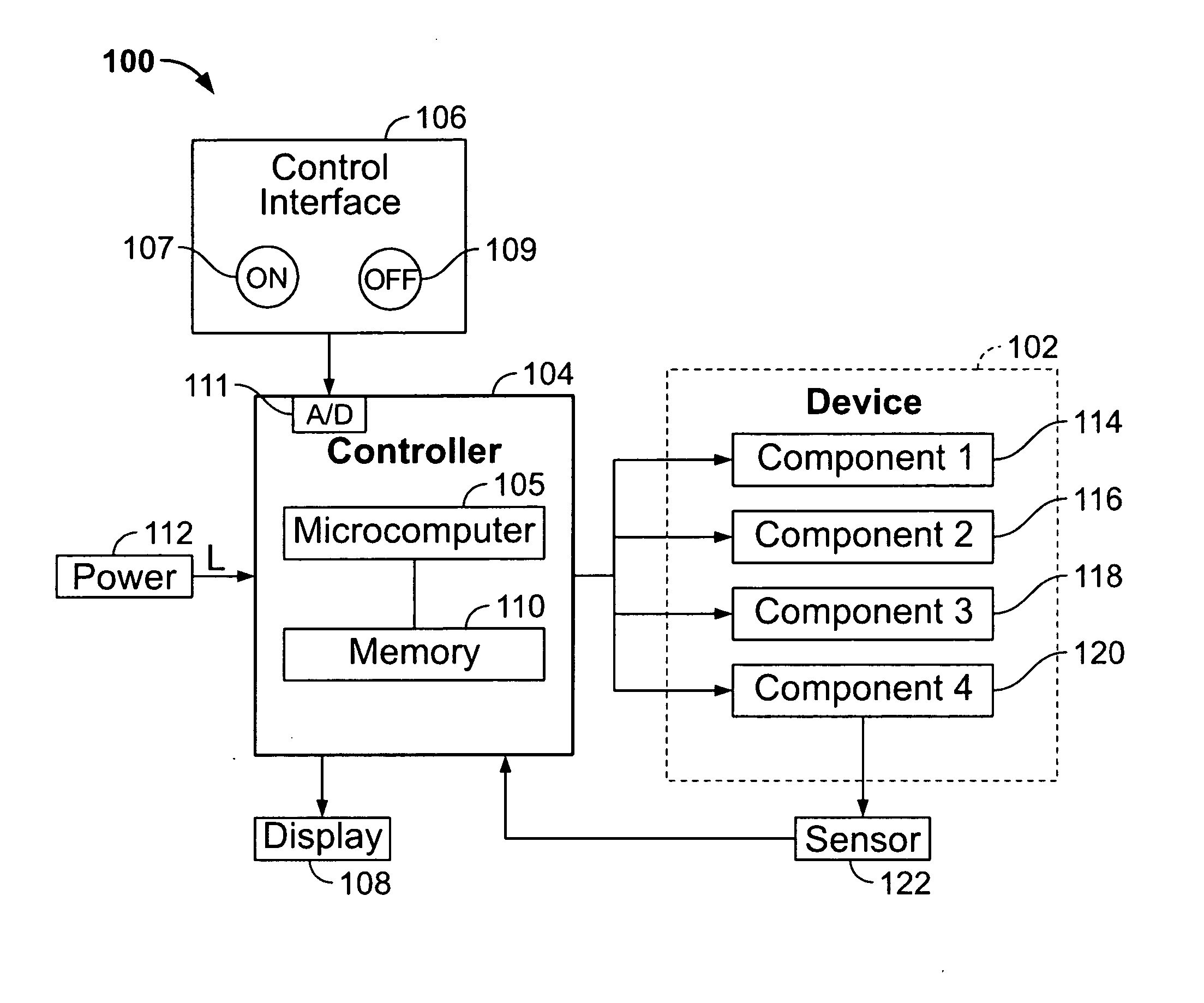
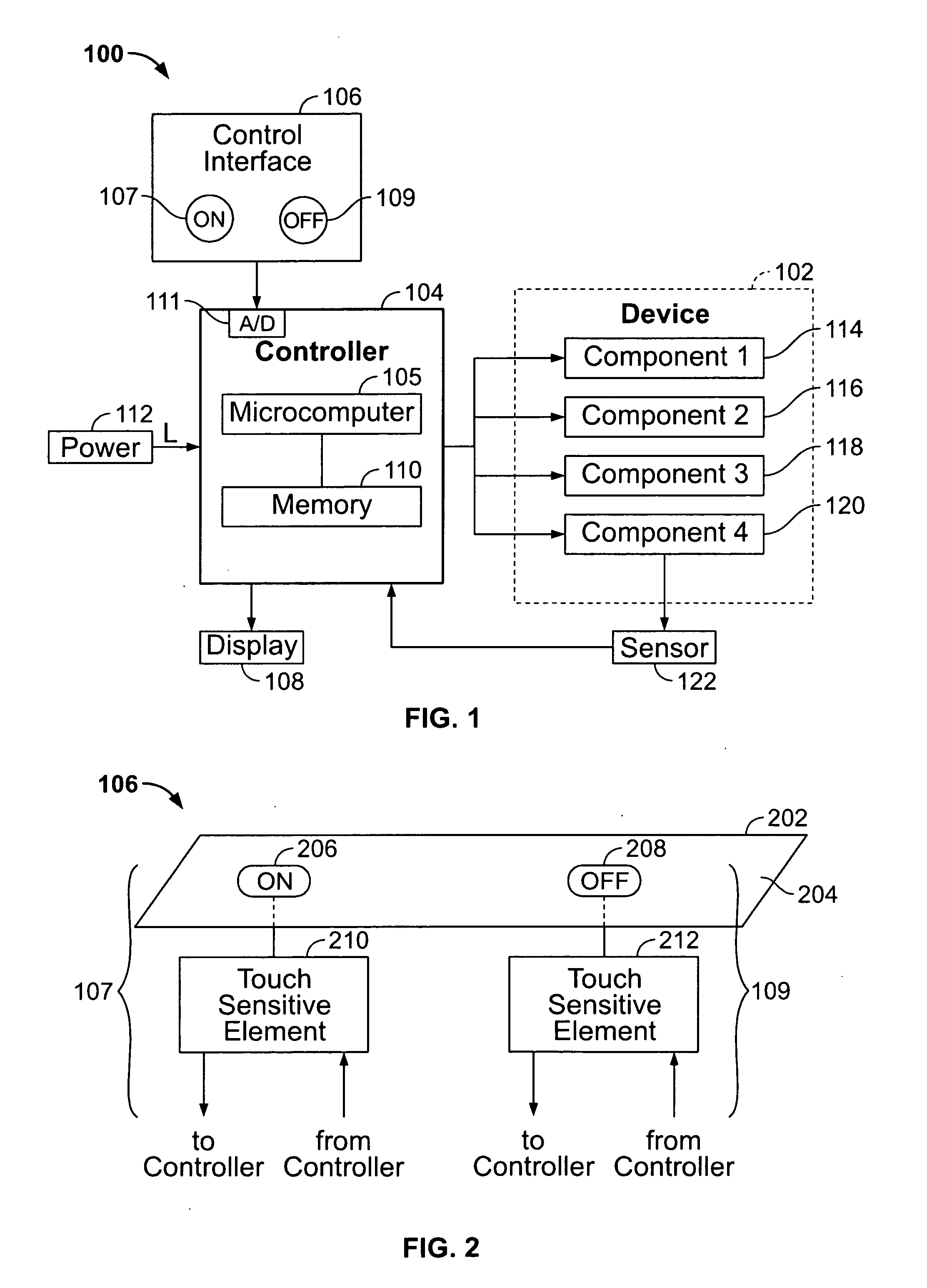
[0018]FIG. 1 is a schematic block diagram of an exemplary touch sensitive control system 100 in accordance with an exemplary embodiment of the invention. The control system 100 includes a device 102, a controller 104 operatively coupled to the device 102, and a touch control interface 106 for receiving control inputs for operation of the device 102 via the controller 104. As will be described below, the controller 104 is configured to compensate for EMI interference and noise in the ambient environment which could otherwise undesirably influence, activate, or change the control settings of the controlled device 102. It may therefore be assured that the device 102 is operable only with actual user commands entered through the control interface 106.

[0019] In one embodiment, the device 102 is a known vending machine having the touch control interface 106 for operation thereof. In other alternative embodiments, the device 102 may be an appliance, an industrial machine, a toy, or anothe...


PUM


Abstract

A touch sensitive control system for controlling a device includes a touch sensitive interface and a controller configured to communicate with the touch sensitive interface. The control system detects user manipulation of the touch sensitive interface with a touch detection sequence executed by the controller. The touch detection sequence determines a moving average of baseline signal level readings of the touch sensitive interface over time. The touch detection sequence compares a current baseline signal level reading to the moving average of baseline signal level readings, thereby detecting an interference event associated with an unexpectedly high current baseline signal level reading which could otherwise lead to a false touch detection.

Description

BACKGROUND OF THE INVENTION [0001] This invention relates generally to touch sensitive control interfaces, and more particularly, to a touch sensitive control interface including compensation for noise and interference in the ambient environment which may otherwise negatively affect operation of the interface and / or the associated device. [0002] Due to their convenience and reliability, touch sensitive control interfaces are increasingly being used in lieu of mechanical switches for various products and devices. Touch sensitive control interfaces are used in a wide variety of exemplary applications such as appliances (e.g., stoves and cooktops), industrial devices such as machine controls, cash registers and check out devices, vending machines, and even toys. The associated device may be finger operated by pressing predefined areas of the interface, and the device typically includes a controller coupled to the interface to operate mechanical and electrical elements of the device in ...

Claims


Application Information

Patent Timeline
IPC IPC(8): G09G5/00G06F3/041
CPCH03K17/962G06F3/0416
Inventor FRY, CHARLES DAVID
Owner TE CONNECTIVITY CORP
Why Eureka
Try Eureka