System and method of three-dimensional image capture and modeling

a three-dimensional image and modeling technology, applied in the field of three-dimensional (“ 3d”) measuring systems and), can solve the problems of increasing computation time, not well-suited to mesh constructions, and reducing the overall accuracy of models

Inactive Publication Date: 2006-10-12
ANDREAS ACQUISITION LLC
View PDF5 Cites 37 Cited by
  • Summary
  • Abstract
  • Description
  • Claims
  • Application Information

AI Technical Summary

Benefits of technology

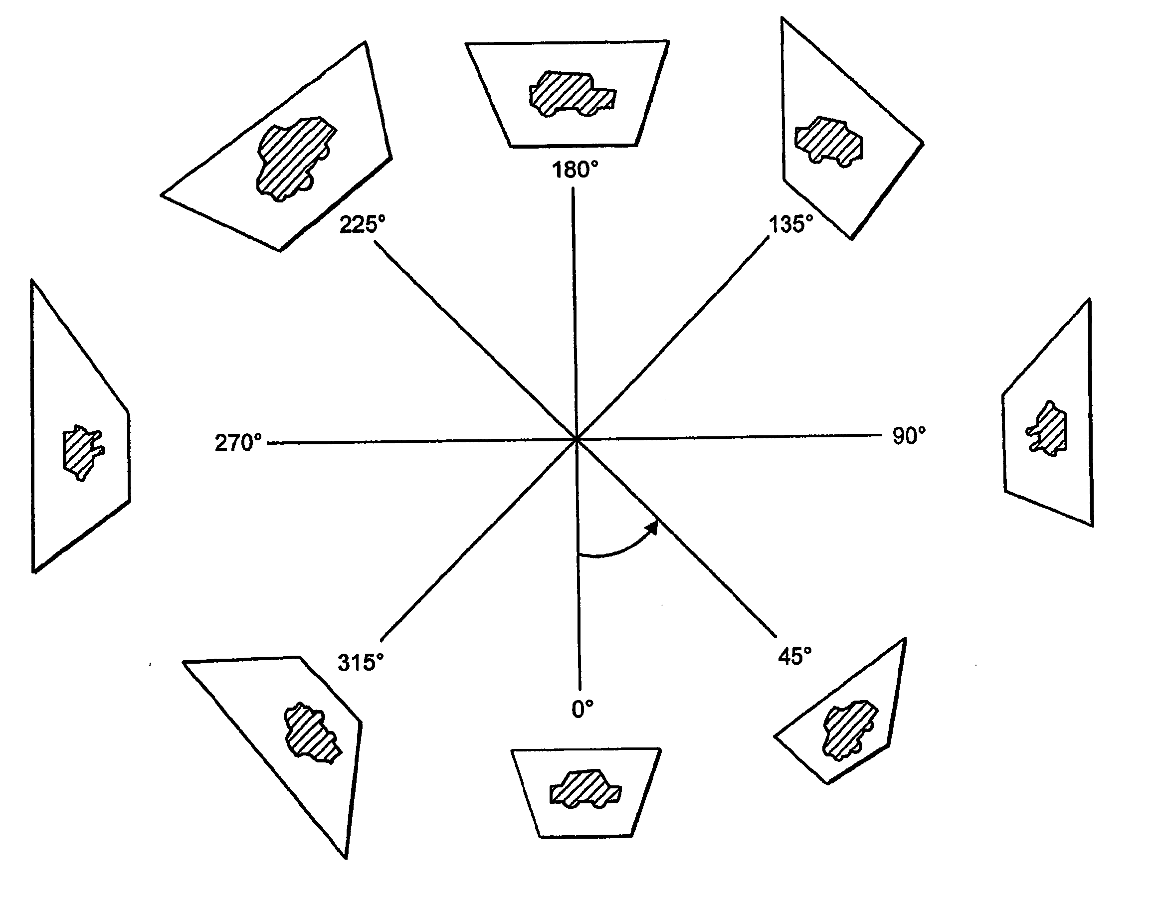
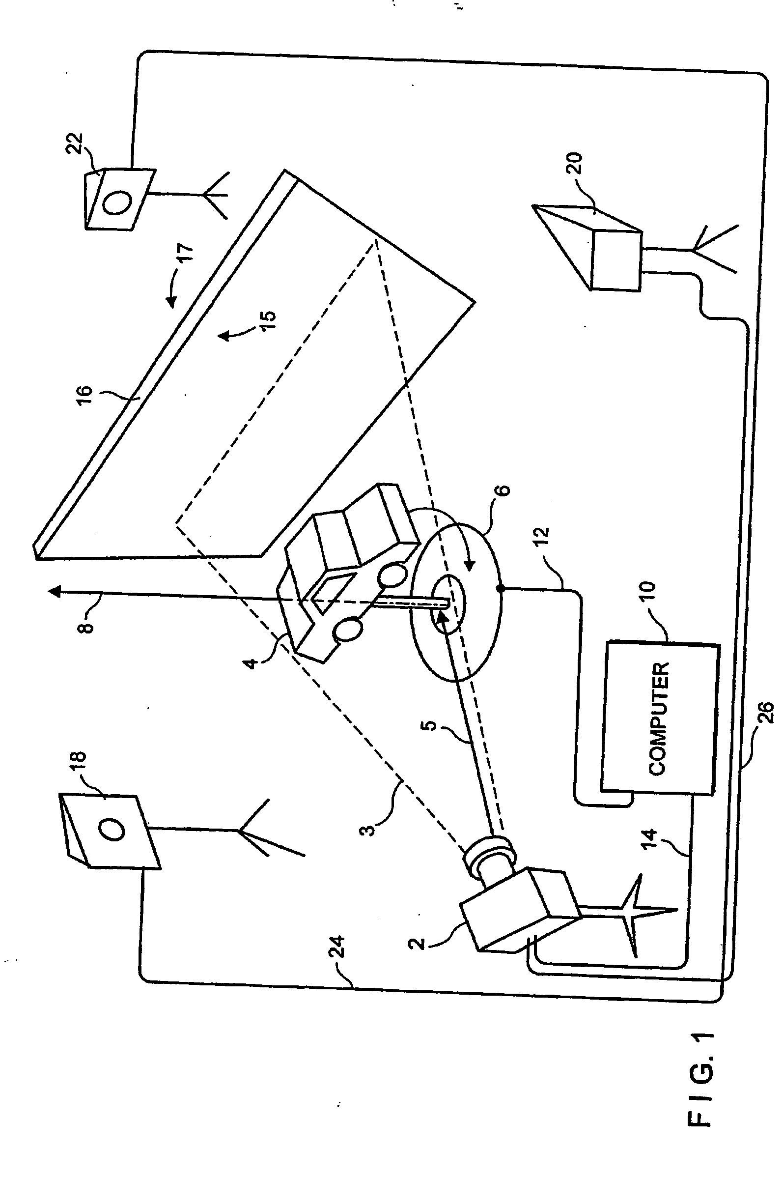
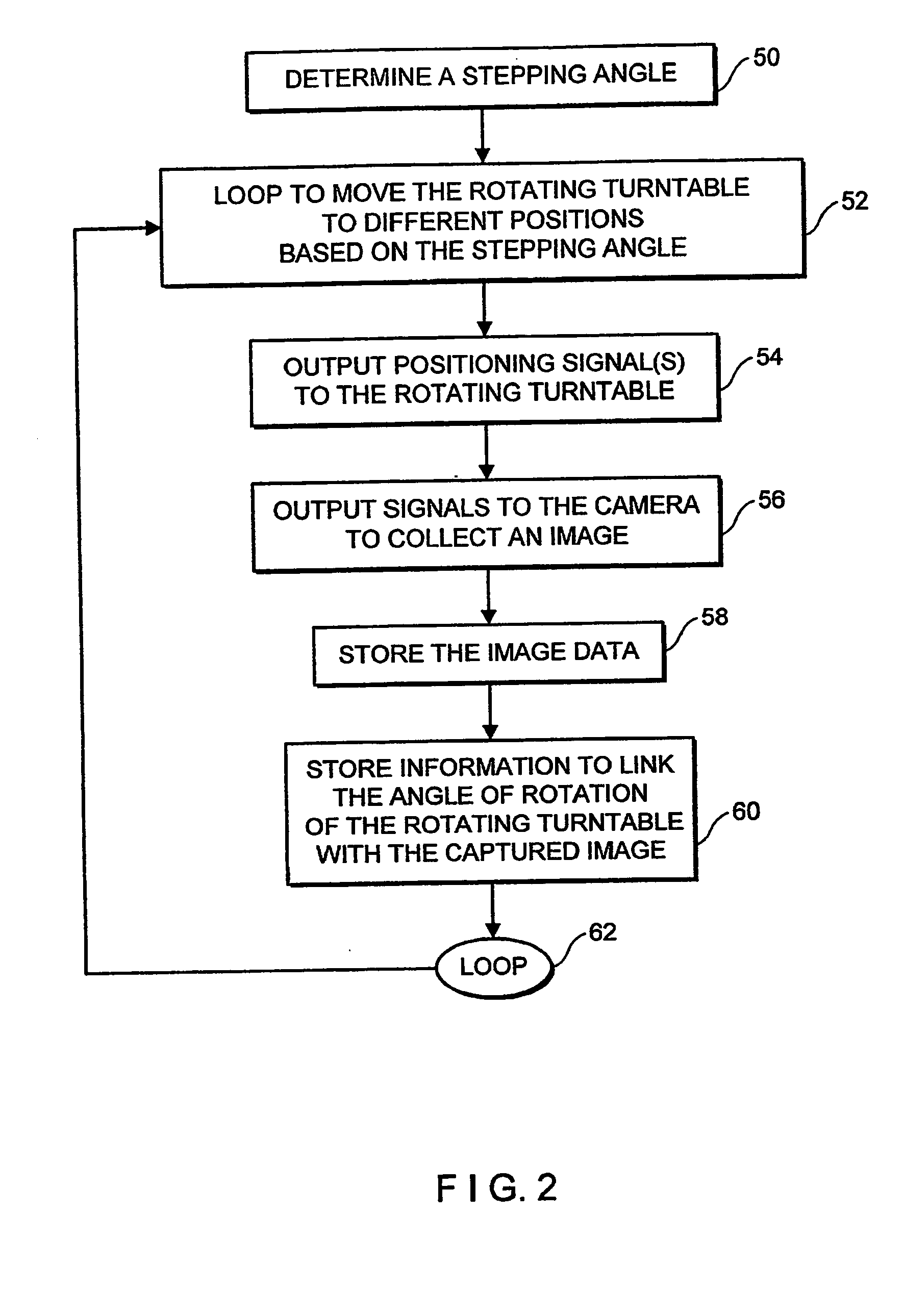
[0020] The present invention provides a system and method for constructing a 3D model of an object based on a series of silhouette and texture map images. One aspect of the present invention is a system and method for capturing silhouette and texture images which eliminates the need for special backgrounds, such as a brightly colored green or blue background. In two related image-taking sequences, a camera takes spatial (mesh construction) data in one pass and then texture data in a second image-taking pass.
[0023] The image capture process of the present invention enables users to create 3D models that are highly accurate in terms of their spatial dimensions and also highly accurate in terms of their texture map color. The use of distinct passes for capturing mesh construction and, separately, texture data, also eliminates the need to use colored backgrounds, such as green backgrounds, during image capture.
[0027] By computing the dimensions of the object analytically in the overlaying process—by finding the areas of intersection of the silhouette and model outlines—the present invention eliminates the need for a gridded block in determining the spatial contours of the 3D model. The present invention also provides a more accurate representation of the shape as compared to those systems which incorporate a gridded block, as the points of the contour lines do not have to be anchored to the cubic grid points.

Problems solved by technology

While gridded models provide regular, predictable structures, they are not well-suited for mesh constructions based on an irregular set of data points, such as those generated through laser scanning or silhouette capture.
The need to interpolate an irregular set of data points into a regular grid structure increases computation time and decreases the overall accuracy of the model.
However, the use of brightly or specifically colored backgrounds (such as using an all green background) also introduces a level of error into the modeling procedure.
Thus, the 3D model created from the processing of such object modeling systems will sometimes be inaccurate, because those models will have some of the background color residue included in their texture.
Further, in such an instance the reflection of such a green light color against the object can also hamper the system's efforts to collect the spatial data concerning the object.
Such systems will sometimes have additional difficulty determining if a point within an image belongs to the object or the background—especially if the object has (or is radiating) a patch of color that is the same as the background.
The use of a volumetric approach can also cause difficulties in processing and inaccuracies in the final object model.
This approach has the limitation that it is necessary to start with a fixed-sized grid.
The use of the grid limits the resolution of the final 3D object model to the resolution of the grid.

Method used


Image

  • System and method of three-dimensional image capture and modeling
  • System and method of three-dimensional image capture and modeling
  • System and method of three-dimensional image capture and modeling

Examples


embodiment

6. Generating 3D Coordinates (Alternative Embodiment)

[0409] Once the polygonal shape building module 1668 has generated vertices for each object-related shape in a silhouette mask image, the 3D coordinate module 1670 determines a 3D X, Y, Z real world spatial coordinate for each of those vertices. This module also associates those 3D coordinates with each vertex of the polygon so that for each vertex of the polygon, the procedure stores the values of the X, Y, Z coordinates as well as the x, y location of the vertex in the silhouette mask image object (e.g. 1604).

[0410] In the exemplary embodiment, the 3D coordinate module 1670 of the present invention determines 3D coordinates by a triangulation process. An example of a similar triangulation process is described in U.S. Pat. No. 6,044,170, the entire disclosure of which is expressly incorporated herein by reference.

[0411] To calculate X, Y, Z coordinates, the 3D coordinate module 1670 uses values for the focal length L of the cam...


PUM


Abstract

System and method for constructing a 3D model of an object based on a series of silhouette and texture map images. In the exemplary embodiment an object is placed on a rotating turntable and a camera, which is stationary, captures images of the object as it rotates on the turntable. In one pass, the system captures a number of photographic images that will be processed into image silhouettes. In a second pass, the system gathers texture data. After a calibration procedure (used to determine the camera's focal length and the turntable's axis of rotation), a silhouette processing module determines a set of two-dimensional polygon shapes (silhouette contour polygons) that describe the contours of the object. The system uses the silhouette contour polygons to create a 3D polygonal mesh model of the object. The system determines the shape of the 3D model analytically by finding the areas of intersection between the edges of the model faces and the edges of the silhouette contour polygons. The system creates an initial, (rough) model of the 3D object from one of the silhouette contour polygons, then executes an overlaying procedure to process each of the remaining silhouette contour polygons. In the overlaying process, the system processes the silhouette contour polygons collected from each silhouette image, projecting each face of the (rough) 3D model onto the image plane of the silhouette contour polygons. The overlaying of each face of the (rough) 3D model onto the 2D plane of the silhouette contour polygons enables the present invention to determine those areas that are extraneous and should be removed from the (rough) 3D model. As the system processes the silhouette contour polygons in each image it removes the extraneous spaces from the initial object model and creates new faces to patch “holes.” The polygonal mesh model, once completed, can be transformed into a triangulated mesh model. In a subsequent step, the system uses a deterministic procedure to map texture from the texture images onto the triangles of the 3D mesh model, locating that area in the various texture map images that is “best” for each mesh triangle.

Description

[0001] This application claims the benefit of U.S. Provisional Application No. 60 / 192,506, entitled “System and Method of Three Dimensional Image Capture and Modeling”, filed Mar. 28, 2000.FIELD OF THE INVENTION [0002] This invention relates to three-dimensional (“3D”) measuring systems and the imaging and modeling of objects and other 3D surfaces by computer. In particular, this invention relates to systems and methods for measuring and reproducing objects and other 3D surfaces by the capture and computer processing of photographic images which contain “silhouette” views of the object or surface. COPYRIGHT NOTICE [0003] Portions of this patent document contain material which is subject to copyright protection. The copyright owner has no objection to the facsimile reproduction by anyone of the patent document or patent disclosure as it appears in the Patent and Trademark Office patent file or records, but otherwise reserves all copyright rights whatsoever. BACKGROUND [0004] There is...

Claims


Application Information

Patent Timeline
Patent Type & Authority Applications(United States)
IPC IPC(8): G06T15/00G06F17/00G06T1/00G06V10/10
CPCG06K2209/40G06K9/20G06V10/10G06V2201/12
Inventor PETROV, MICHAELMIGDAL, ALEXANDERLEBEDEV, ALEXEISHELYEKHOVA, VERONIKAPOLONSKIY, LEONIDABADJEV, VADIM
Owner ANDREAS ACQUISITION LLC
Why Eureka
Try Eureka