Light scatter measurement apparatus and method

a light scatter measurement and light scatter technology, applied in the field of optical characterization, can solve the problems of progressive diffusion of the circulating beam about the path, measurement errors inherent in this technique, and less accurate conventional light intensity based measurements

Inactive Publication Date: 2006-10-12
THE BOEING CO
View PDF9 Cites 1 Cited by
  • Summary
  • Abstract
  • Description
  • Claims
  • Application Information

AI Technical Summary

Problems solved by technology

As the reflectivity or transmission increase, conventional light intensity based measurements become less accurate and other methods are used instead.
However, measurement errors inherent with this technique can be significant.
Irregularities on the surface of the test piece result in a progressive diffusion of the circulating beam about the path.

Method used


Image

  • Light scatter measurement apparatus and method
  • Light scatter measurement apparatus and method
  • Light scatter measurement apparatus and method

Examples


Embodiment Construction

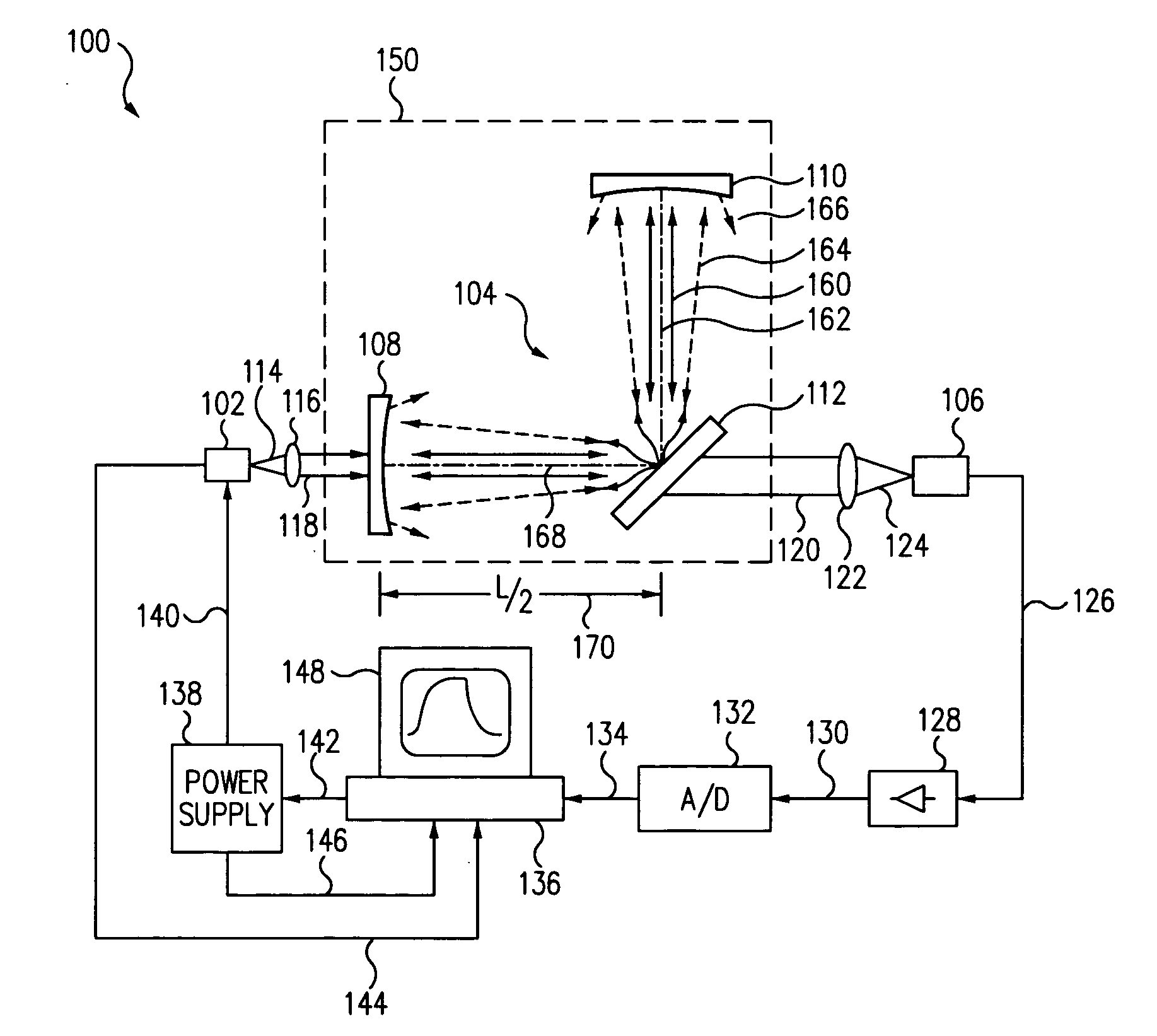
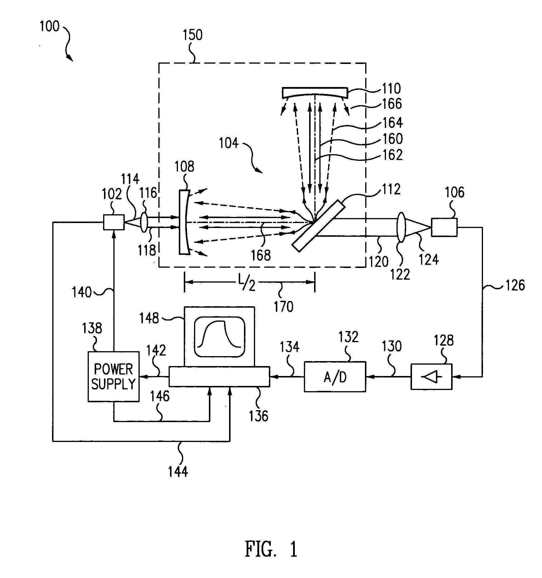
[0025] In reference to FIG. 1, an optical scatter measurement system 100 includes a light source 102, a passive optical cavity 104, and a detector 106. Light source 102 provides a light beam to excite the cavity 104. In this embodiment, the cavity 104 includes a first end mirror 108, a second end mirror 110, and a test piece 112 configured to form an L-shaped arrangement where the end mirrors form the legs of cavity 104 and are located symmetrically about the test piece.

[0026] In this embodiment, the legs are spaced at 90-degrees so that test piece 112 is located at about 45-degrees having a normal that bisects the angular distance between the two legs of cavity 104. End mirrors (108, 110) each have a planar surface and a highly reflective concave surface. The test piece 112 has a reflective planar surface facing the cavity and can be set at a 45-degree angle to form the L-shaped cavity 104 where the concave surface of the first end mirror 108 is oriented towards the planar surface...


PUM

PropertyMeasurementUnit
round trip timeaaaaaaaaaa
diametersaaaaaaaaaa
diametersaaaaaaaaaa

Abstract

In accordance with an embodiment of the present invention, an apparatus for measuring light scatter loss from a test piece includes a light source, an optical cavity including the test piece and at least one mirror located along a path, and a light detector. The cavity receives an input beam from the light source, circulates a beam within the cavity as a circulating beam, and produces an output beam. Irregularities on the surface of the test piece result in a progressive diffusion of the circulating beam about the path. The light detector provides an output signal based on the intensity of the output beam. The output signal has an initial slope that determines a first saturation value. The output signal has a second saturation value. The difference between the first saturation value and the second saturation value provides a scatter loss measurement.

Description

TECHNICAL FIELD [0001] The present invention relates generally to optical characterization, and more particularly to determining the scatter loss from a surface. RELATED ART [0002] The characterization of an optical surface, such as a high performance optical dielectric coating, can include the determination of losses due to reflection, transmission, absorption, and light scatter. As the reflectivity or transmission increase, conventional light intensity based measurements become less accurate and other methods are used instead. One alternative method, utilizes a passive cavity decay time property known as a cavity ringdown technique. In this method, a coated test piece or test article is introduced into a passive optical resonant cavity where the observed change in cavity decay time is related to the additional losses induced by the test article coating. This technique only provides a measure of the total cavity losses which include, for a highly reflective coating, absorption, tra...

Claims


Application Information

Patent Timeline
Patent Type & Authority Applications(United States)
IPC IPC(8): G01N21/47
CPCG01N21/4738
Inventor CLARK, ROY
Owner THE BOEING CO
Why Eureka
Try Eureka