DC-DC converter

Active Publication Date: 2006-10-12
PANASONIC CORP
View PDF3 Cites 100 Cited by
  • Summary
  • Abstract
  • Description
  • Claims
  • Application Information

AI Technical Summary

Benefits of technology

[0008] The object of the present invention is

Problems solved by technology

Use of a high-frequency insulating converter in such a power converter would cause

Method used


Image

  • DC-DC converter
  • DC-DC converter
  • DC-DC converter

Examples


Example

[0033] Hereinafter, referring to the accompanying drawings, a DC-DC converter according to an embodiment of the present invention and an interconnected inverter using the DC-DC converter will be explained.

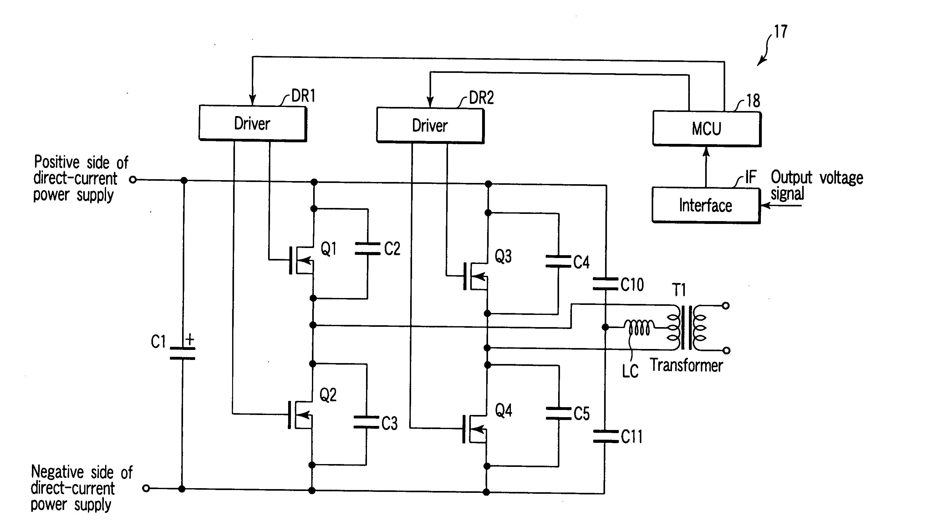
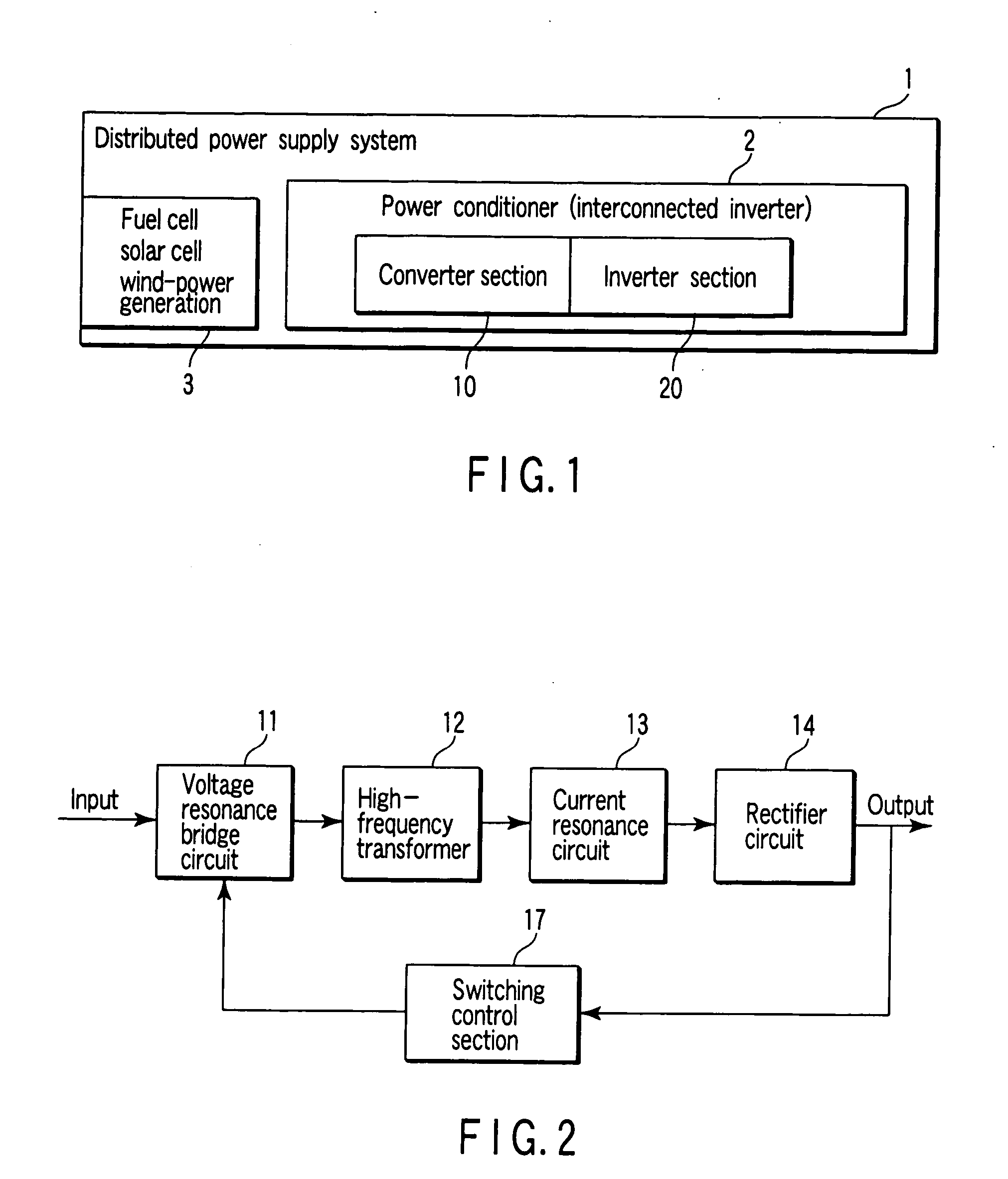
[0034]FIG. 1 schematically shows the configuration of a distributed power system to which an interconnected inverter 2 composed of a converter section 10 (DC-DC converter) according to an embodiment of the present invention and an inverter section 20 that performs DC-AC conversion is applied.

[0035] In the distributed power system of FIG. 1, the output (direct-current electric power) of a direct-current power supply 3 whose output fluctuates, such as a fuel cell, a solar cell, or wind-power generation, is input to an interconnected inverter acting as a power conditioner and then is subjected to DC-DC conversion at the converter section of the interconnected inverter. The converted DC output is converted at the inverter section 20 into a relatively small alternating-current output ...


PUM


Abstract

There is provided a high-efficiency DC-DC converter which comprises a voltage resonance circuit to which electric power from a low-voltage direct-current power supply, including a household fuel cell and a solar cell, is input and performs DC-AC conversion by zero-voltage switching, an insulating high-frequency transformer which transmits the converted power, a current resonance circuit which is provided on the secondary side of the transformer and performs zero-current switching, a rectifier circuit which rectifies the output from the current resonance circuit, and a smoothing circuit which rectifies the output from the rectifier circuit.

Description

CROSS REFERENCE TO RELATED APPLICATIONS [0001] This is a Continuation Application of PCT Application No. PCT / JP2005 / 004824, filed Mar. 17, 2005, which was published under PCT Article 21(2) in Japanese. [0002] This application is based upon and claims the benefit of priority from prior Japanese Patent Applications No. 2004-119652, filed Mar. 18, 2004; and No. 2004-272503, filed Sep. 17, 2004, the entire contents of both of which are incorporated herein by reference. BACKGROUND OF THE INVENTION [0003] 1. Field of the Invention [0004] This invention relates to a DC-DC converter. More particularly, this invention relates to an insulating DC-DC converter for a distributed power supply which converts electric power from a distributed direct-current power supply into a medium amount of electric power and an interconnected inverter which uses the DC-DC converter. [0005] 2. Description of the Related Art [0006] A distributed power supply system which converts electric power from a distribute...

Claims


Application Information

Patent Timeline
IPC IPC(8): H02M3/335H02M3/28H02M7/12
CPCH02J2001/004H02M3/33523H02M3/3376H02M2001/0012Y02B10/14H02J3/383H02J3/386Y02E10/563Y02E10/763H02M2001/0077H02J2300/30H02J2300/28H02J2300/24H02J3/381Y02B10/10Y02E10/56Y02E10/76H02M1/0012H02M1/0077H02M7/05
Inventor HORIUCHI, SHOJINAKAMURA, YOSHIMICHITAN, NOZOMI
Owner PANASONIC CORP
Why Eureka
Try Eureka