Power converter system and method

a power converter and power supply technology, applied in the direction of power conversion systems, ac-ac conversion, dc source parallel operation, etc., can solve the problems of reducing availability, shutting down the entire power converter system, and the converter output voltage is not of high quality

Inactive Publication Date: 2006-10-12
GENERAL ELECTRIC CO
View PDF8 Cites 188 Cited by
  • Summary
  • Abstract
  • Description
  • Claims
  • Application Information

AI Technical Summary

Problems solved by technology

A single point failure in such converter systems may lead to the shutting down of the entire power converter system, thereby lowering

Method used


Image

  • Power converter system and method
  • Power converter system and method
  • Power converter system and method

Examples


Embodiment Construction

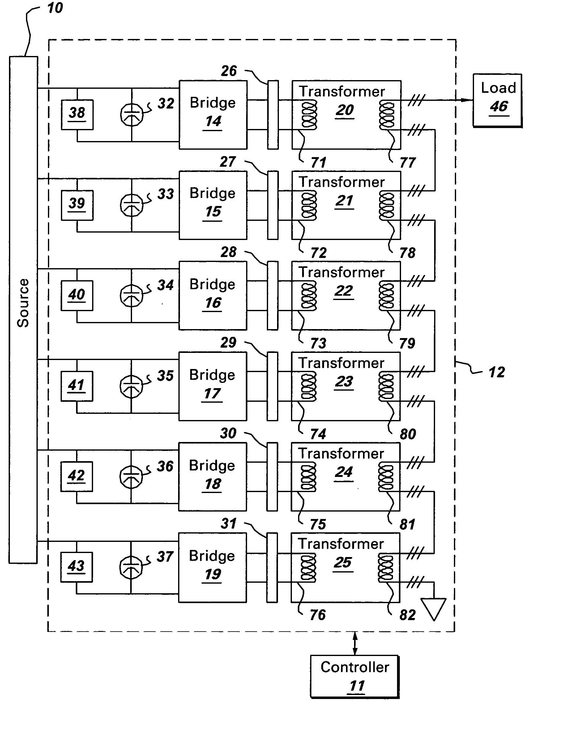
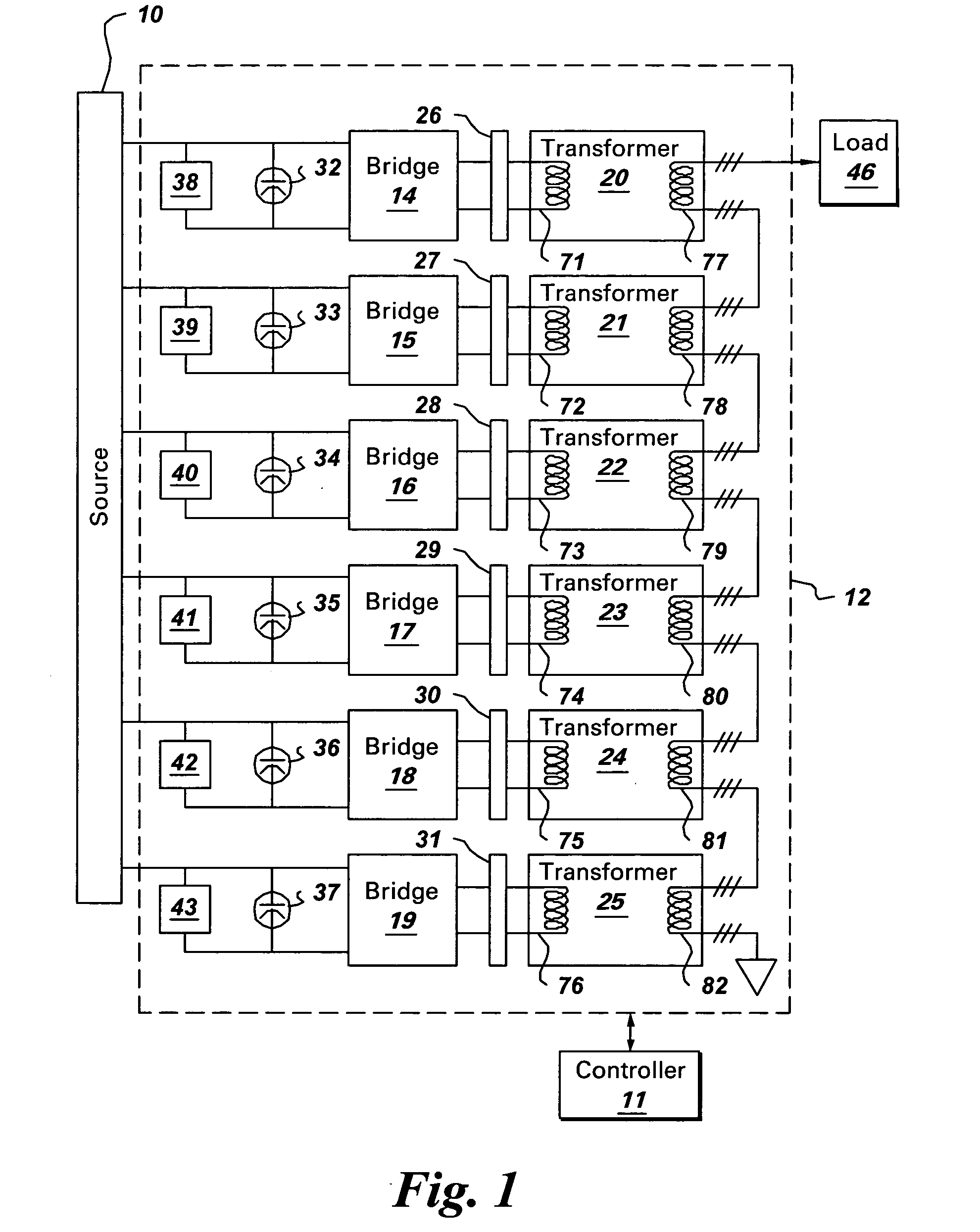
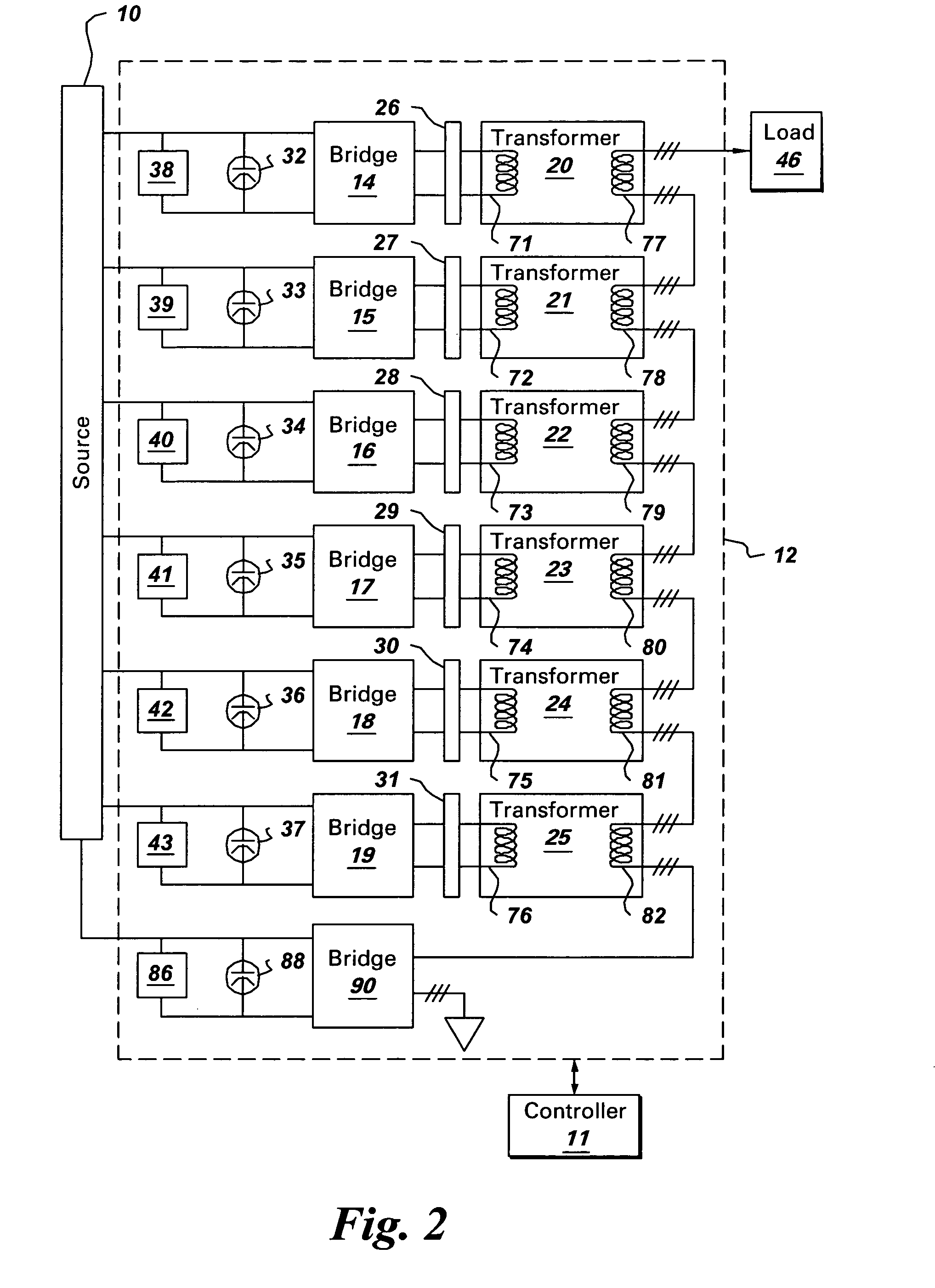
[0015]FIG. 1 is a block diagram of a power converter system implemented according to one aspect of the invention. Power converter system 12 is configured to convert dc power to corresponding ac power, which is then provided to load 46. In the illustrated embodiment, source 10 provides dc power to the power converter system. Examples of the source include electrical machines, fuel cells, a capacitor or ultra-capacitor based dc link energy storage, and batteries. Examples of loads include grids, motors, and resistive loads. Power converter system 12 is configured to operate n a normal mode and a fault mode. The power converter system 12 is described in further detail below.

[0016] As used herein, “adapted to”, “configured” and the like refer to features of elements in a system which allow the elements of the system to cooperate to provide a described effect; these terms also refer to operation capabilities of electrical elements such as analog or digital computers or application speci...


PUM


Abstract

A power converter system for supplying an output voltage is provided. The power converter system is adapted to operate in a normal mode and a fault mode. The system comprises a plurality of bridges and a plurality of transformers. The system further comprises a plurality of dc link capacitors, each coupled across a corresponding bridge. The system also includes a controller adapted for, during the normal mode, switching each bridge with a respective normal phase shift. During the fault mode, the controller is adapted for switching each of the remaining ones of the bridges with a respective adjusted phase shift to generate the output voltage. During the fault mode, at least one of the plurality of bridges is bypassed.

Description

BACKGROUND [0001] The invention relates generally to power converter systems and more specifically to a method and system for operating a power converter system in a normal mode and a failure mode. [0002] Many devices, such as power supply systems, include power converter systems. A power converter system is typically used to convert an input voltage, which may be fixed frequency, variable frequency, or dc to a desired converter output voltage. The output voltage and frequency may be fixed or variable. A converter system usually includes several switches such as insulated gate bipolar transistors (IGBTs) that are switched at certain frequencies to generate the desired converter output voltage and frequency. The converter output voltage is then provided to various loads via transformers. Loads as used herein are intended to broadly include motors, power grids, and resistive loads, for example. [0003] In several applications such as wind power generation and industrial power generatio...

Claims


Application Information

Patent Timeline
IPC IPC(8): H02J1/10H02M7/49
CPCH02M7/49H02M7/48
Inventor DATTA, RAJIBCHEN, KUNLUNWENG, HAIQINGRAJU, RAVISEKHAR NADIMPALLI
Owner GENERAL ELECTRIC CO
Why Eureka
Try Eureka