Method for mounting a rotor blade of a wind power installation without using a crane

a technology for wind power installations and rotor blades, which is applied in the field of mounting a rotor blade of a wind power installation without a crane, can solve the problems that the cost involved in such stationary crane installations is scarcely reasonably related to the benefit, and achieve the effect of not consuming a great deal of time and cos

Active Publication Date: 2006-10-12
WOBBEN ALOYS
View PDF5 Cites 34 Cited by
  • Summary
  • Abstract
  • Description
  • Claims
  • Application Information

AI Technical Summary

Benefits of technology

[0014] If the wind power installation has three rotor blades, it is advantageous if one of the cables is carried by a (rotatable) shaft or a shaft trunnion of the wind power installation so that, upon rotation of the hub, that cable always remains taut and does not have to be set up afresh in order to prepare the blade mounting procedure for a further rotor blade.
[0015] Only the cable which is held in the front part of the hub, the so-called spinner, has to be transposed upon rotation of the hub through 120° (in the case of a rotor with three rotor blades) in such a way that, for the blade mounting operation, the cable is disposed parallel to the rotor blade connection of the hub to be fitted with the blade, and is oriented vertically. Such conversion however is relatively simple and can be effected without a very great deal of time and cost.

Problems solved by technology

A disadvantage of mobile cranes is that they must always be on site when the rotor blades are to be mounted to the hub of the wind power installation with such cranes.
A disadvantage of stationary cranes is that usually they can also only be mounted on the machine housing of the wind power installation by means of a mobile crane and in addition, if such stationary cranes remain on the machine housing, they are only extremely rarely used so that the costs involved with such stationary crane installations are scarcely reasonably related to the benefit thereof.

Method used


Image

  • Method for mounting a rotor blade of a wind power installation without using a crane
  • Method for mounting a rotor blade of a wind power installation without using a crane

Examples


Embodiment Construction

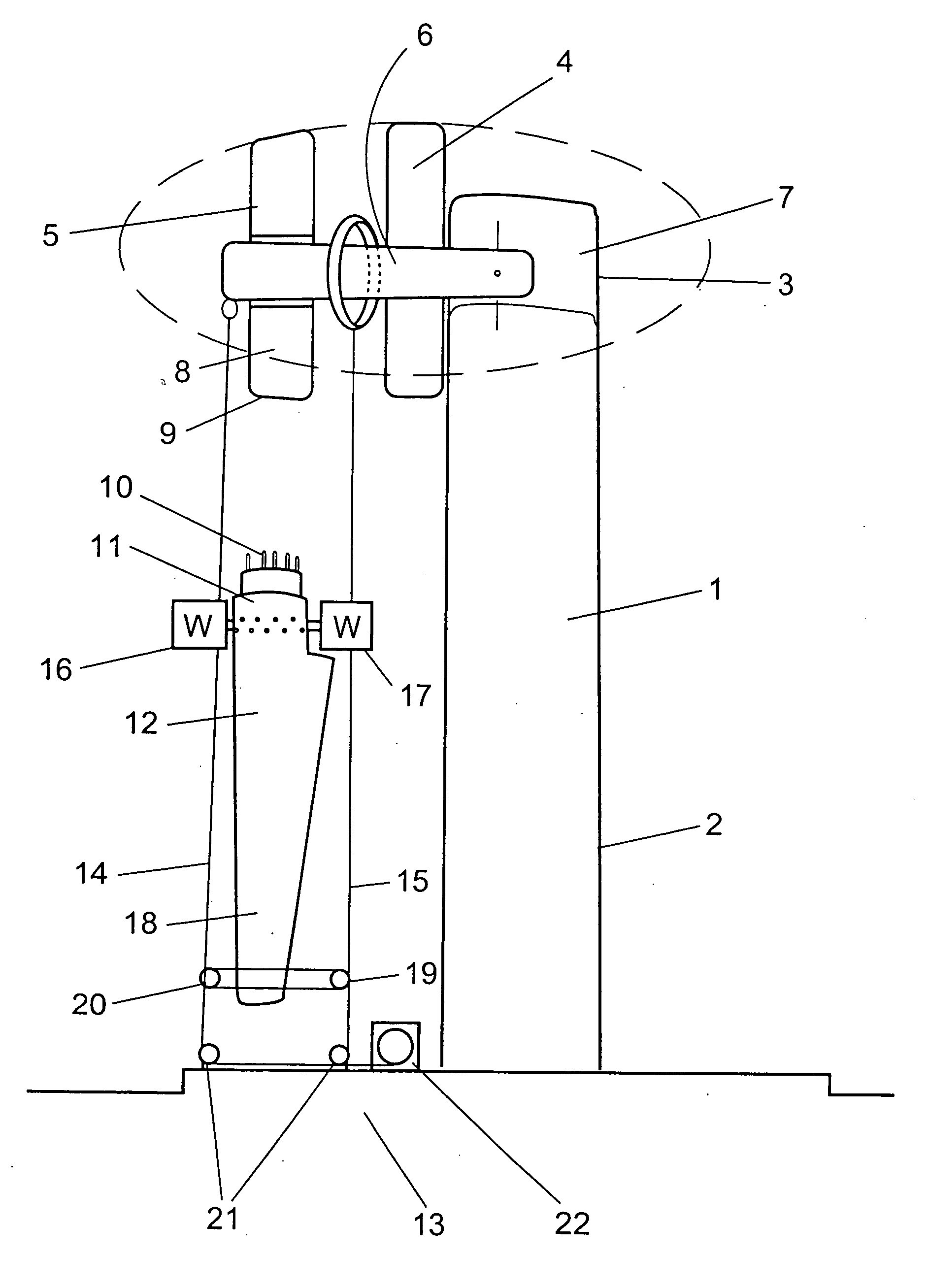
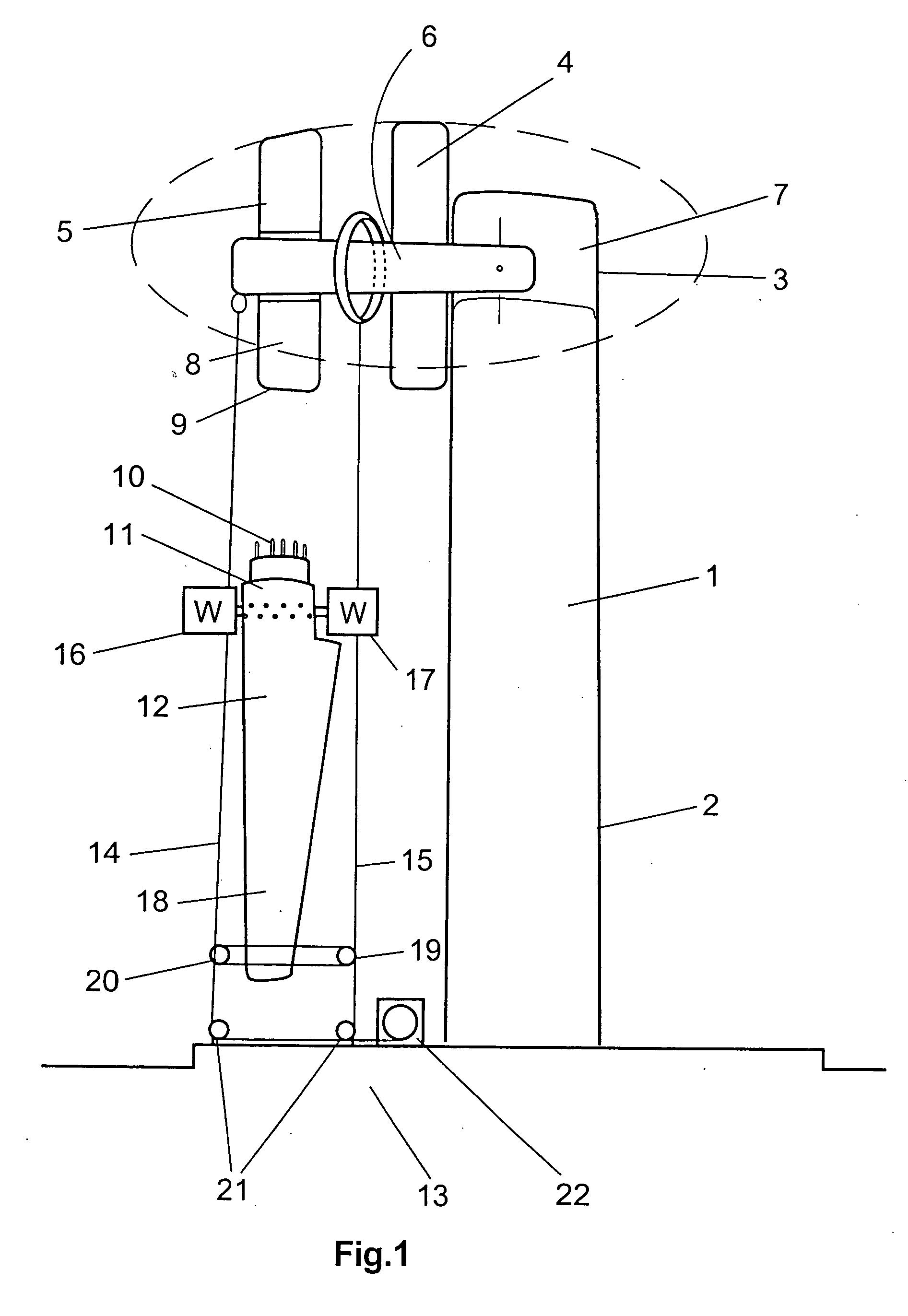
[0017]FIG. 1 shows a side view of a wind power installation 1 comprising a pylon 2 and a machine housing 3 which is disposed on the pylon and which accommodates a generator 4 and a rotor 5 with a hub 8, the generator and the rotor being held by a shaft trunnion 6 which is mounted on a machine carrier 7 of the machine housing. The hub 8 itself has a rotatably mounted rotor blade connection 9 having an annular flange with a plurality of bores, through which screw bolts 10 on the connecting flange 11 of the rotor blade 12 can be fitted in the mounting procedure, so that the rotor blade can be screwed to the rotor blade connection of the hub by fitting nuts on the screw bolts. The rotor blade connection is further provided with a usual pitch drive (not shown) in order in that way to rotate the entire rotatable part of the rotor blade to a desired pitch angle.

[0018] Two cables 14, 15 are stretched substantially parallel to each other and parallel to the pylon 2 from the hub region 8 of ...


PUM

PropertyMeasurementUnit
rotationaaaaaaaaaa
timeaaaaaaaaaa
pitch angleaaaaaaaaaa

Abstract

It has already long been known to use mobile cranes for mounting rotor blades to a wind power installation. Such cranes pick up the rotor blade at the base of the wind power installation and take it to the rotor blade connection of the hub of the wind power installation so that the rotor blade can be connected to the hub. That connection is usually made by screw means, in which case screw bolts are let into the connecting flange of the rotor blade and project into corresponding bores in the rotor blade connection of the hub so that nuts can be screwed on to the screw bolts. The object of the invention is attained by a blade mounting method having the features of claim 1. Advantageous developments are set forth in the appendant claims. A method of mounting or dismantling a rotor blade of a wind power installation without using a crane to a rotor blade connection on a hub of a rotor of the wind power installation, wherein at least one cable is stretched between a part in the hub region of the wind power installation and the bottom region of the wind power installation and the rotor blade is moved along the cable upwardly upon mounting or downwardly upon dismantling.

Description

BACKGROUND OF THE INVENTION [0001] 1. Field of the Invention [0002] The invention concerns a method for mounting a rotor blade of a wind power installation without using a crane and a wind power installation implementing said method. [0003] 2. Description of the Related Art [0004] It has already long been known to use mobile cranes for mounting rotor blades to a wind power installation. Such cranes pick up the rotor blade at the base of the wind power installation and take it to the rotor blade connection of the hub of the wind power installation so that the rotor blade can be connected to the hub. That connection is usually made by screw means, in which case screw bolts are let into the connecting flange of the rotor blade and project into corresponding bores in the rotor blade connection of the hub so that nuts can be screwed on to the screw bolts and in that way the rotor blade is fixed to the hub. [0005] As published state of the art attention is directed in particular to the bo...

Claims


Application Information

Patent Timeline
Patent Type & Authority Applications(United States)
IPC IPC(8): F04D29/00F03D1/00
CPCF03D1/001F03D1/003F05B2230/60Y10T29/49316Y02E10/721Y02E10/728F05B2240/916F03D13/10F03D80/50F03D1/00Y02E10/72Y02P70/50
Inventor WOBBEN, ALOYS
Owner WOBBEN ALOYS
Why Eureka
Try Eureka