Drive system for a crop conveying device

a technology of conveying device and drive system, which is applied in the direction of solid separation, sieving, screening, etc., can solve the problems of complex and technologically advanced device used in the conveying unit of the self-propelled agricultural machine to separate crop material, and achieve the effect of simple functional geometry

Inactive Publication Date: 2006-10-12
CLAAS SELBSTFAHRENDE ERNTEMASCHINEN GMBH
View PDF23 Cites 76 Cited by
  • Summary
  • Abstract
  • Description
  • Claims
  • Application Information

AI Technical Summary

Benefits of technology

[0013] The present invention is therefore based on the object of creating a drive system for a crop conveying unit of the type described initially that prevents the aforementio

Problems solved by technology

The crop conveying unit used to separate crop material in a self-propell

Method used


Image

  • Drive system for a crop conveying device
  • Drive system for a crop conveying device
  • Drive system for a crop conveying device

Examples


Embodiment Construction

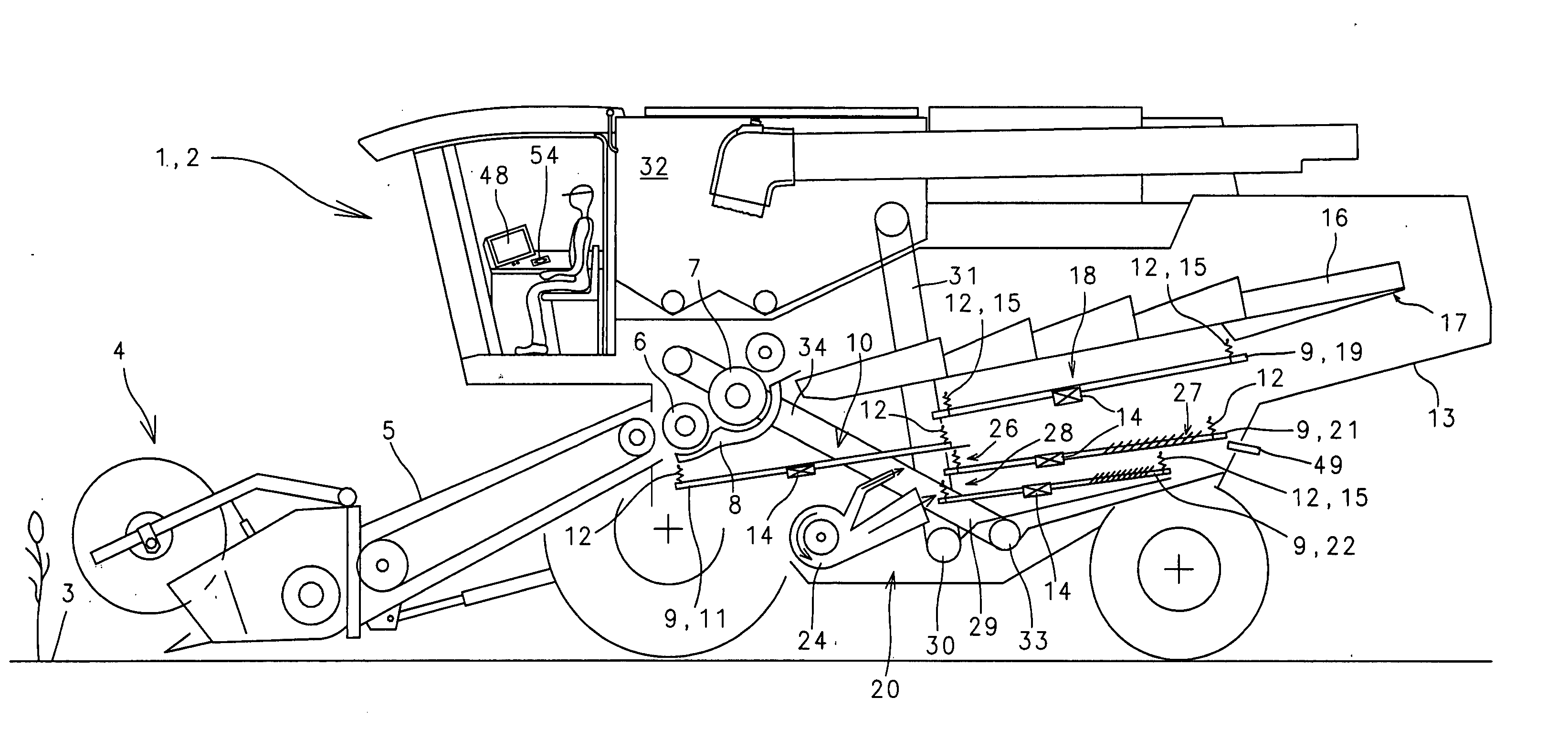
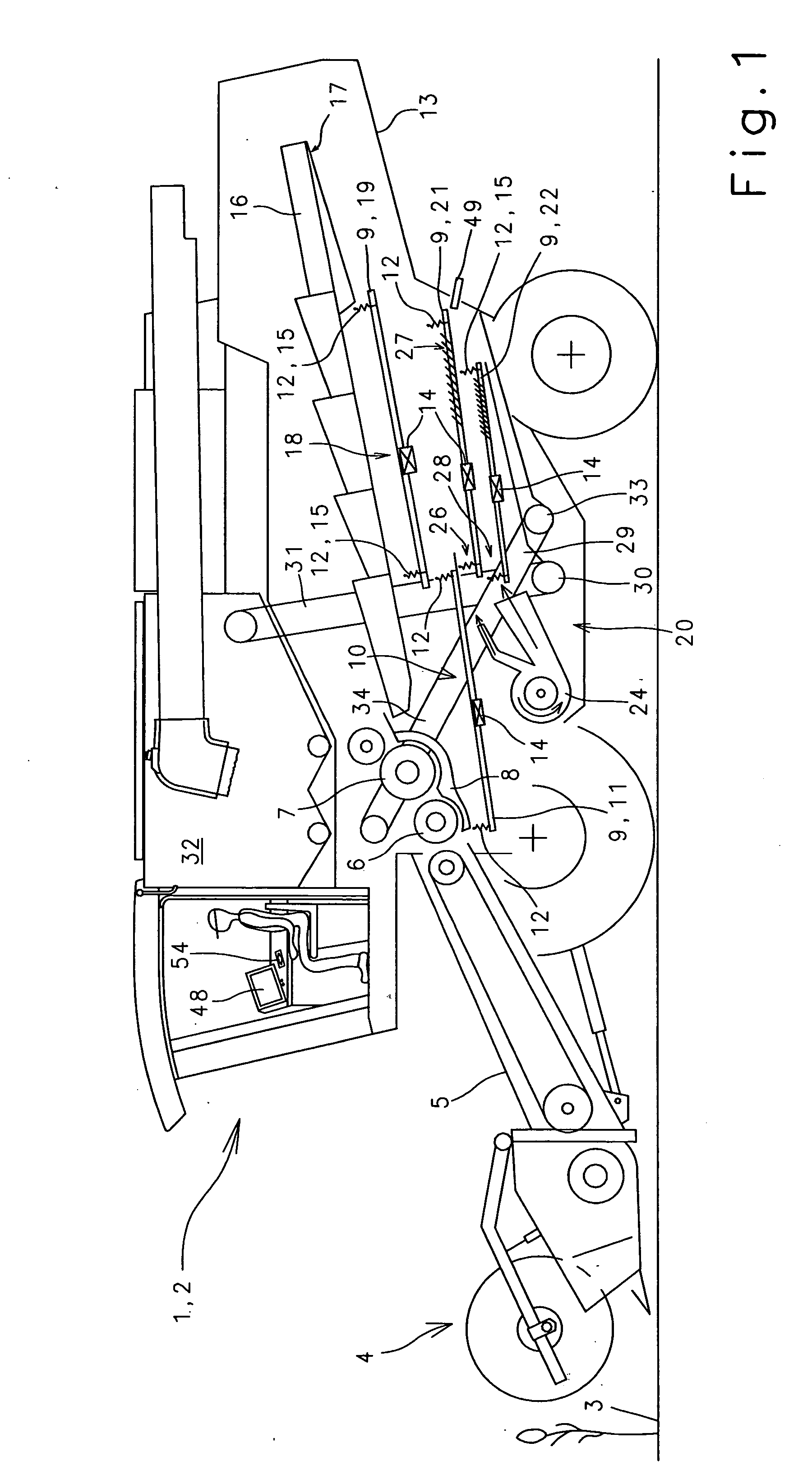
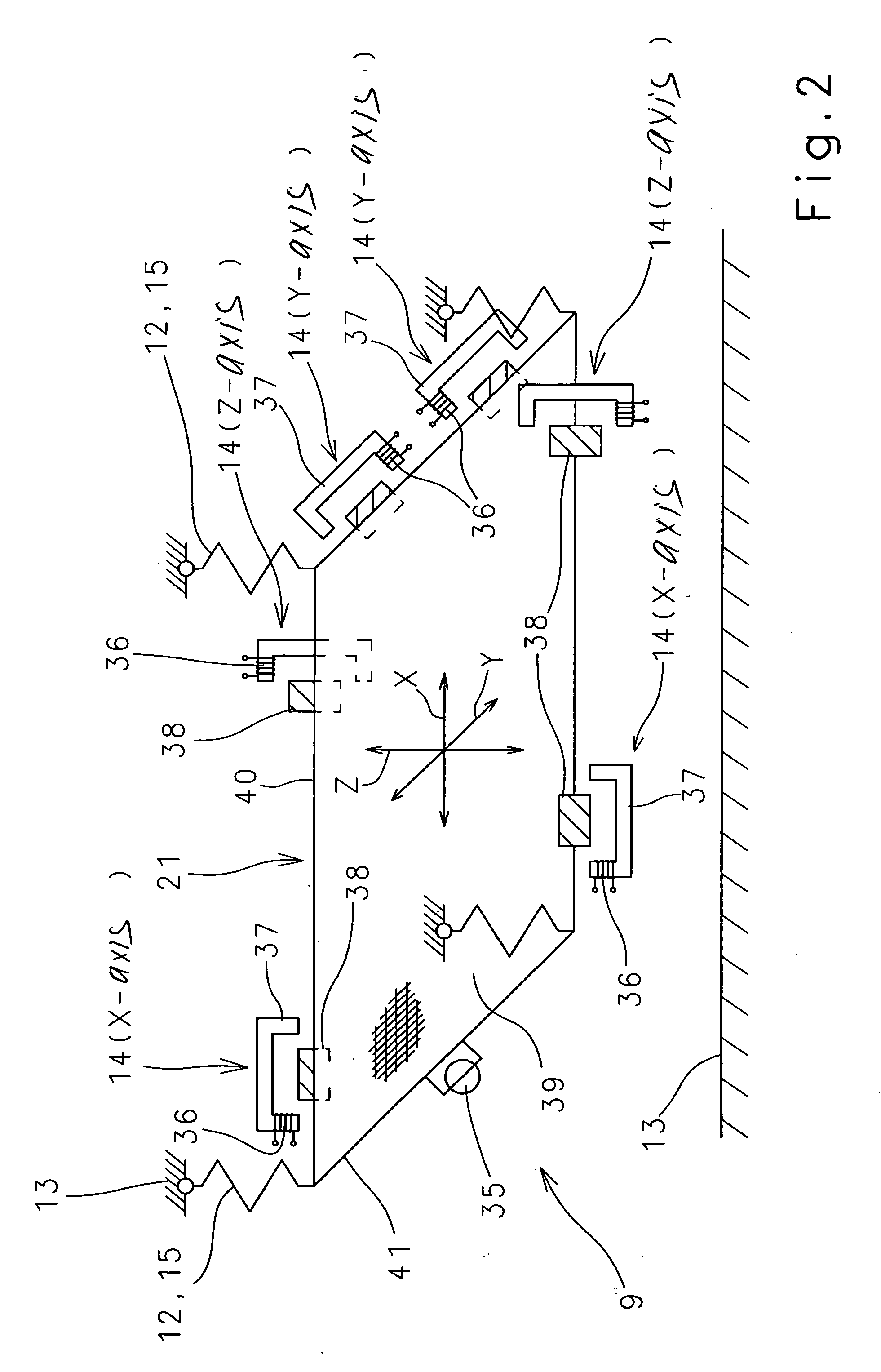
[0040]FIG. 1 shows a schematized side view of a combine harvester 2, combine harvester 2 including a method and device used to drive a crop conveying device 9 composed mainly of at least one pan 11 and at least one sieve 21, the pan 11 and sieve 21 each being hung in an oscillation-facilitating manner in machine housing 13, and at least one oscillation-inducing drive unit 14, drive unit 14 being formed by a linearly-oscillating swinging unit 14 and being controlled via a change in frequency and / or stroke.

[0041] The object of a combine harvester 2 is to pick up the crop material from a field 3 and separate it into grain and non-grain components. A header 4 and a conveyor 5 are provided for picking up and processing the crop material, conveyor 5 directing the crop material to threshing unit 6, 7. The initial separation of the grain from the ears and straw takes place in thresing unit 6, 7. The grains pass through concave 8 to the grain pan of crop conveying unit 9, crop conveying uni...


PUM


Abstract

In a method and a device for driving a crop conveying unit composed substantially of at least one pan with at least one sieve the pen and receive are hung in an oscillation-facilitating manner in a machine housing, at least one oscillation-reducing drive unit is provided, drive unit is formed by a linearly-oscillation unit, and the drive unit is controlled via a change in a parameter selected from the group consisting of frequency, stroke, and both.

Description

BACKGROUND OF THE INVENTION [0001] The present invention relates to the field of processing harvested crops in general. [0002] Self-propelled agricultural machines designed to pick up and process crops, e.g., corn or different types of grain, are used for this purpose. The self-propelled agricultural machines are typically threshing machines, in particular combine harvesters, which are equipped with devices for processing the crop material. To process the crop material, which is composed of a mixture of grain material and non-grain components, devices are used, e.g., to separate the different components of the crop material. A device of this type is, e.g., a crop conveying device, which is composed of a fan unit, a conveyance device, a return device and a cleaning unit with an upper sieve and a lower sieve located in a sieve pan, the crop conveying unit including a drive unit. [0003] With a combine harvester of this type, the harvested crop material is directed by the feed device to...

Claims


Application Information

Patent Timeline
IPC IPC(8): A01F12/32
CPCA01D75/282A01F12/446A01F12/44
Inventor WAMHOF, HEINERHELLENBRAND, FERDINAND
Owner CLAAS SELBSTFAHRENDE ERNTEMASCHINEN GMBH
Why Eureka
Try Eureka