Manipulator

Inactive Publication Date: 2006-10-12
KEIO UNIV
View PDF15 Cites 129 Cited by
  • Summary
  • Abstract
  • Description
  • Claims
  • Application Information

AI Technical Summary

Benefits of technology

[0049] (3) It is possible to improve the rigidity between the operating part and the forceps tip end by providing a coupling member in the middle of the driving rod and to deal with the length of the driving rod even if it is increased.
[0050] (4) It is possible to reduce the speed of the tip end of the link mechanism and hereby increase applied force by mounting the link mechanism on the tip end of the working member and gripping a

Problems solved by technology

The low invasion operation cures diseases by inserting an elongated rod-shaped forceps and a surgical knife from a small hole while watching a diseased part using an endoscope as described above, so that any damage of a normal portion can be reduced to make a contribution to patients, but, on the one hand, there are problems to make difficult the operation of a treatment tool because the tool is restricted by the hole.
However, in order to take an arbitrary attitude the tip end of the forceps requires two or more-degree-of-freedom so that the forceps disclosed in reference 1 does not provide enough operationability.
Further, the forceps disclosed in reference 2 suffers from a difficulty that introduction and operation thereof are difficult in view of the magnitude and costs thereof and a difficulty that satisfactory force feedback cannot be obtained.
For this, the forceps is unlikely to be adopted because

Method used


Image

  • Manipulator
  • Manipulator
  • Manipulator

Examples


Embodiment Construction

[0070] In what follows, an embodiment of the present invention will be described. Although in the following there will be described a case where the present invention is applied to a multi-degree of freedom forceps for operations, it is applicable to manipulators for various applications in each of which it includes an operating part and a working part and the working part is operated in response to the operation of the operating part for various works.

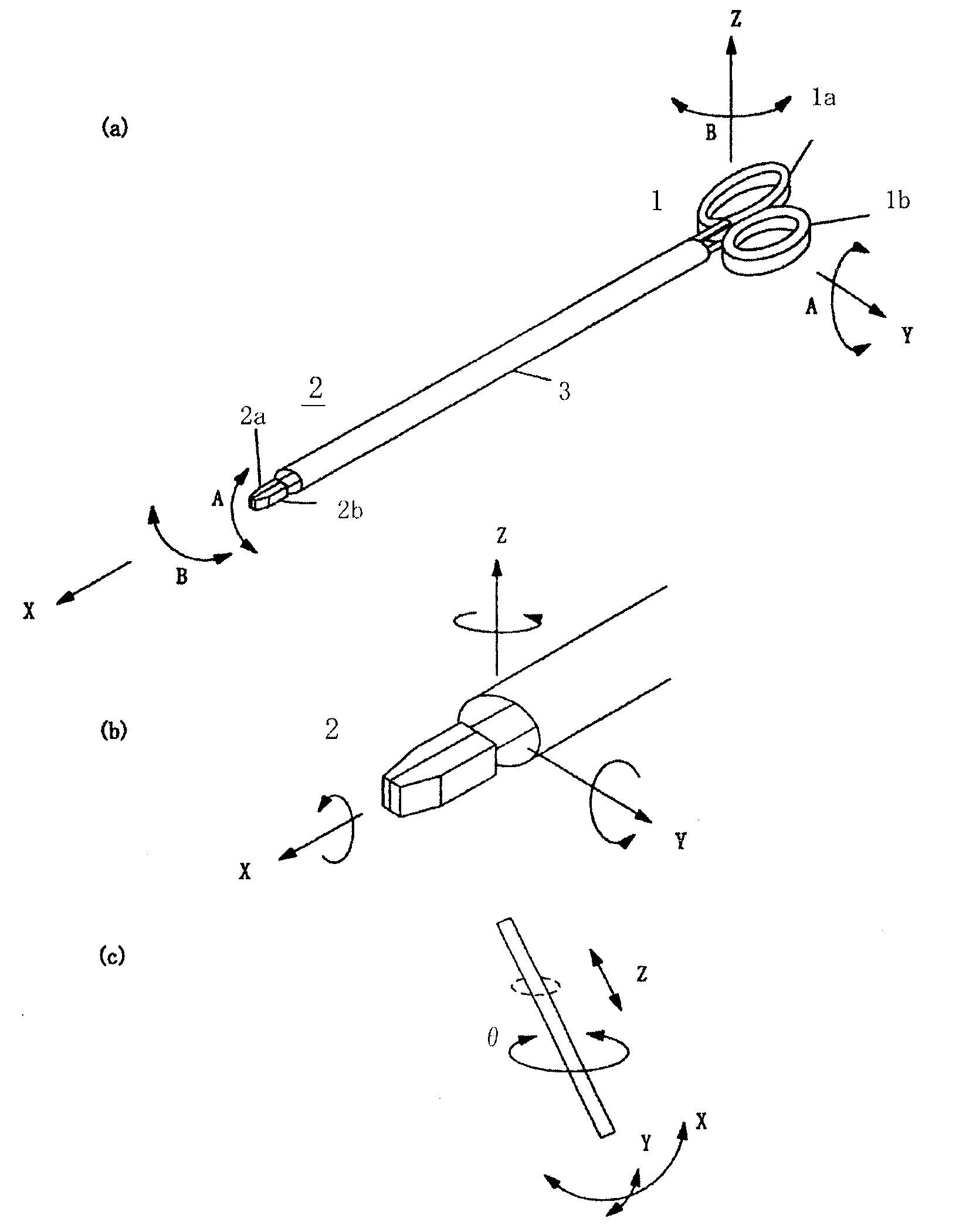
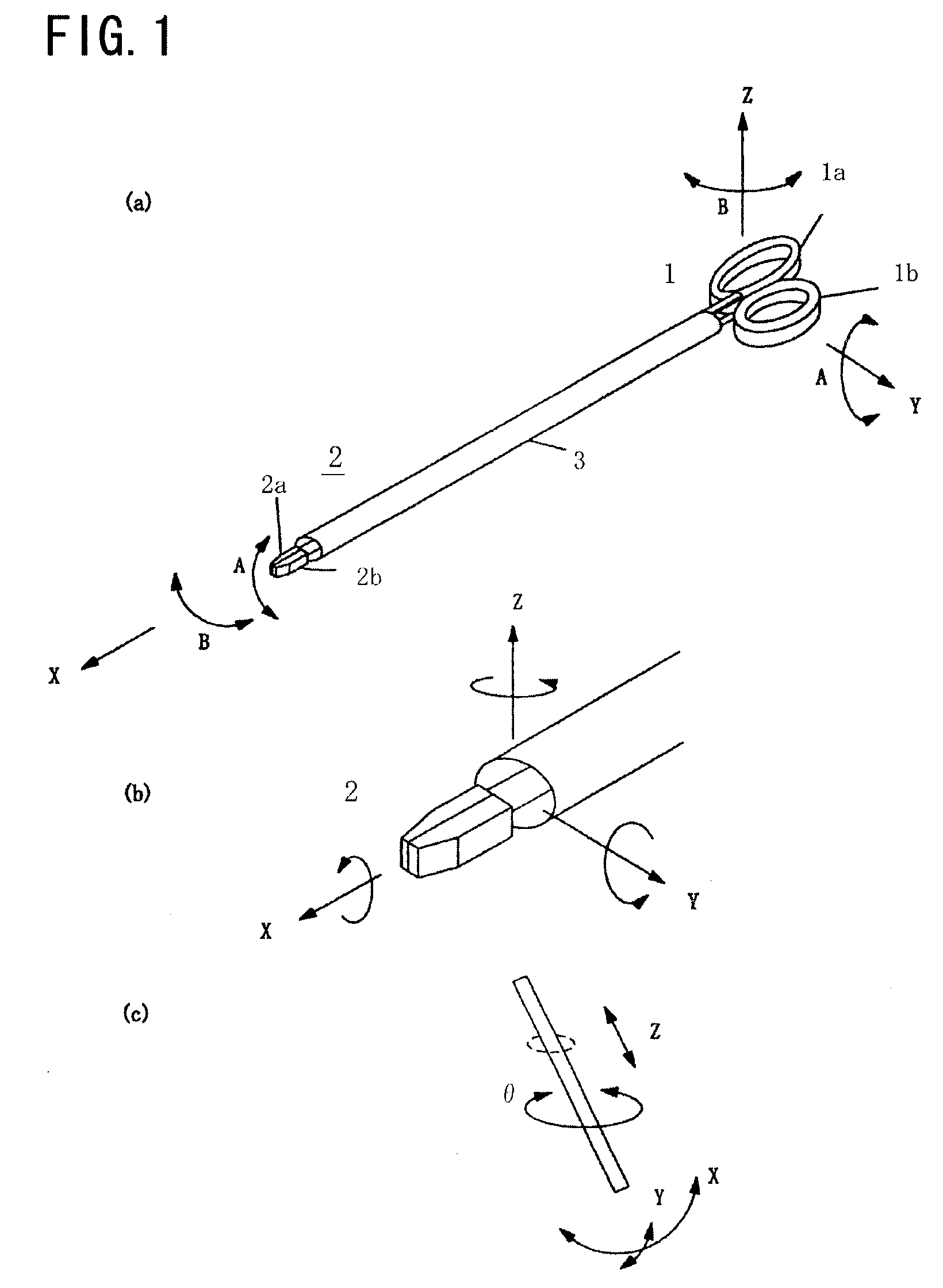
[0071] Referring to FIG. 1 there are illustrated a schematic constitution of a forceps of the embodiment of the present invention and the degree of freedom in the forceps. And the degree of freedom of the forceps of the embodiment will be described.

[0072] In (a) of the same figure, designated at 1 is an operating part and 2 is a working part. The operating part 1 comprises first and second operating parts 1a, 1b, and the working part 2 comprises first and second working members 2a, 2b.

[0073] The operating part 1 and the working par...


PUM


Abstract

There is provided a manipulator simplified in maintenance and operation thereof, the manipulator having the freedom of two-degree-of-freedom of rotation and gripping, and being capable of ensuring force feedback or force sensation with excellent operationability.
A link mechanism 3 is provided between an operating part 1 and a working part 2. The link mechanism 3 comprises four driving rods 3a to 3d and first and second coupling members of the same structure, 41, 42 provided at opposite ends of the driving rods. First and second working members 2a, 2b move correspondingly to operations of first and second operating members 1a, 1b with the aid of the link mechanism 3. For example, provided that the first and second operating members 1a, 1b might be opened and closed, the first and second working members 2a, 2b might be opened and closed (gripping). And also, provided that the first and second operating members 1a, 1b are changed in their yaw angles, the working members 2a, 2b are also correspondingly changed in their yaw angle. Similarly, once the first and second operating members 1a, 1b are changed in their pitch angles, the working members 2a, 2b might be also correspondingly changed in their pitch angles.

Description

CROSS-REFERENCE TO RELATED APPLICATION [0001] This is the priority-claiming application with reference to JP2005-111020 filed on Apr. 7, 2005, based upon U.S. Patent Law, the Article 119 on claiming foreign priority. The following U.S. patent application is hereby incorporated by reference in its entirety as though fully and completely set forth herein: JP2005-111020, filed on Apr. 7, 2005. BACKGROUND OF THE INVENTION [0002] 1. Field of the Invention [0003] The present invention relates to a multiple freedom manipulator preferable to forceps for use in low invasion operation or the like. [0004] 2. Description of the Related Art [0005] Low invasion operations attract many attentions in the field of medical operation and have been introduced into the same in recent years. Although in conventional operations a body of a patient is largely cut as in abdominal surgery the low invasion operation is an operation which is realized only by cutting a body as possible as slightly and in which ...

Claims


Application Information

Patent Timeline
IPC IPC(8): A61B17/00
CPCA61B17/28A61B17/29A61B2017/2939A61B2017/2927A61B2017/2902
Inventor SUZUKI, TAKASHINAKAZAWA, KAZUOMORIKAWA, YASUHIDEKITAJIMA, MASAKI
Owner KEIO UNIV
Why Eureka
Try Eureka