Process for producing winding assembly of dynamo-electric machine and production system of winding assembly
a technology of dynamo-electric machines and winding parts, which is applied in the direction of manufacturing tools, magnetic bodies, instruments, etc., can solve the problems of difficult to change the length the work time of the weaving step becomes long, and the length of the change of the first and the second straight parts is limited, so as to reduce the number of times of weaving
- Summary
- Abstract
- Description
- Claims
- Application Information
AI Technical Summary
Benefits of technology
Problems solved by technology
Method used
Image
Examples
embodiment 1
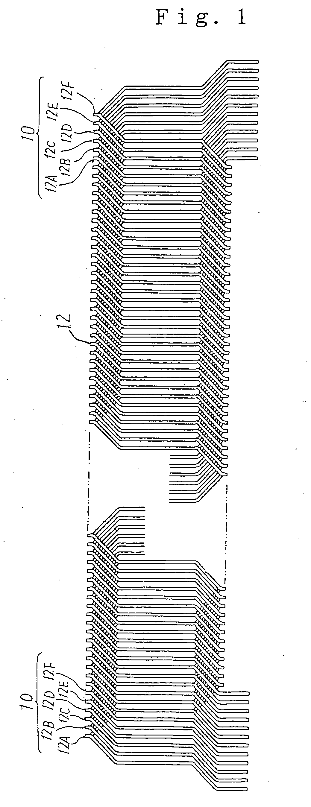
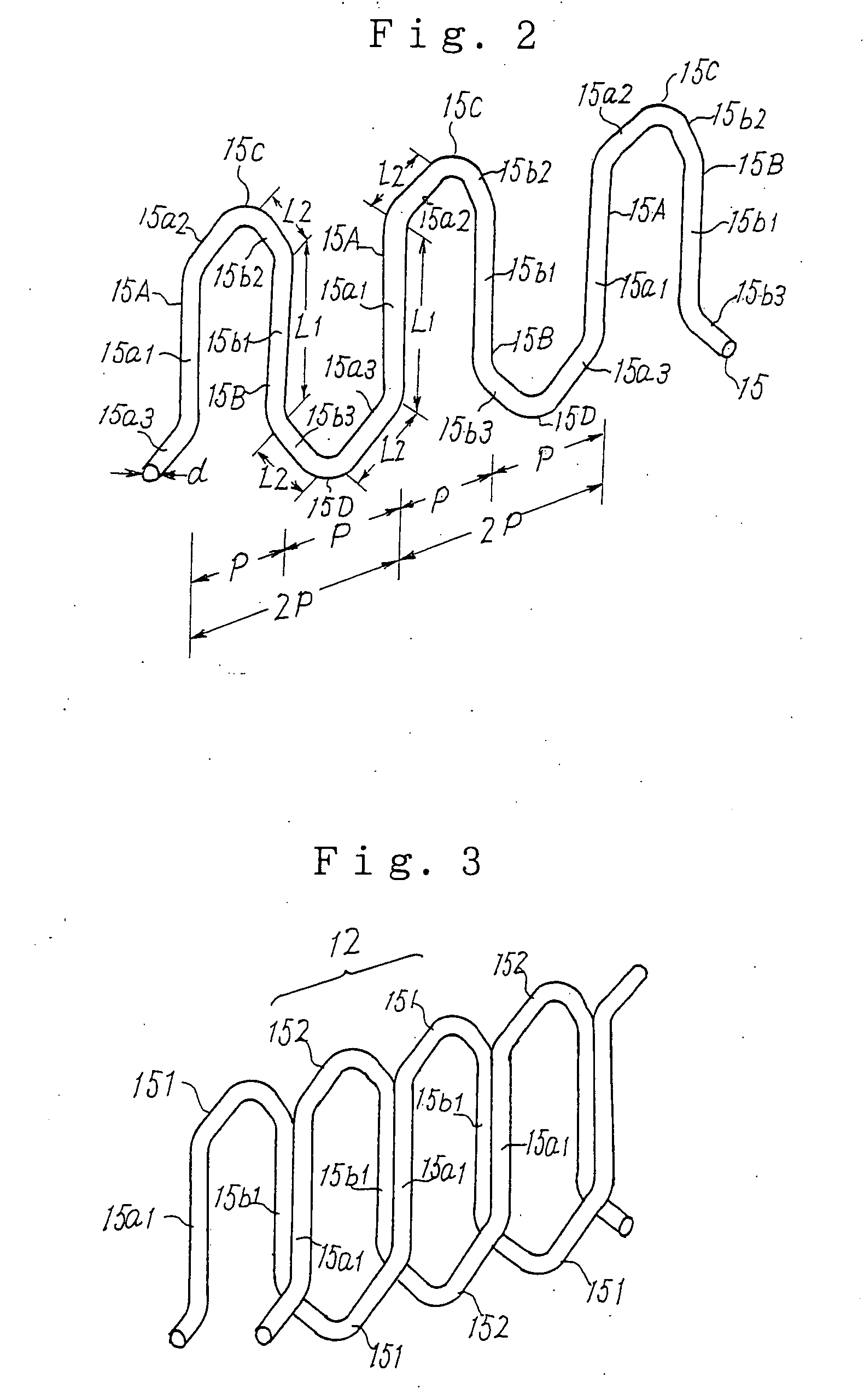
[0065] Embodiment 1 relating to the manufacturing method for the winding assembly 10 of the rotating electrical machine according to this invention will be described.
[0066] The manufacturing method for the winding assembly 10 according to this invention is carried out in the order of a winding step, a displacement step, a press step and an insertion step. First, the winding step of the winding assembly 10 according to this invention will be described, and then, the displacement step, the press step, and the insertion step will be described.
20 Used>
[0067] The main structure of the manufacturing apparatus 20 used in the winding step of embodiment 1 is shown in FIG. 4. FIG. 4(a) is a plan view thereof, and FIG. 4(b) is a side view thereof. As shown in FIGS. 4(a) and 4(b), this manufacturing apparatus 20 includes a turn mechanism 30 and a wire rod feed mechanism 60, and simultaneously and helically winds all twelve winding members 15 constituting the winding assembly 10. Since the win...
embodiment 2
[0111] Next, embodiment 2 of a manufacture method for a winding assembly of a rotating electrical machine according to this invention will be described with reference to FIGS. 16 to 20.
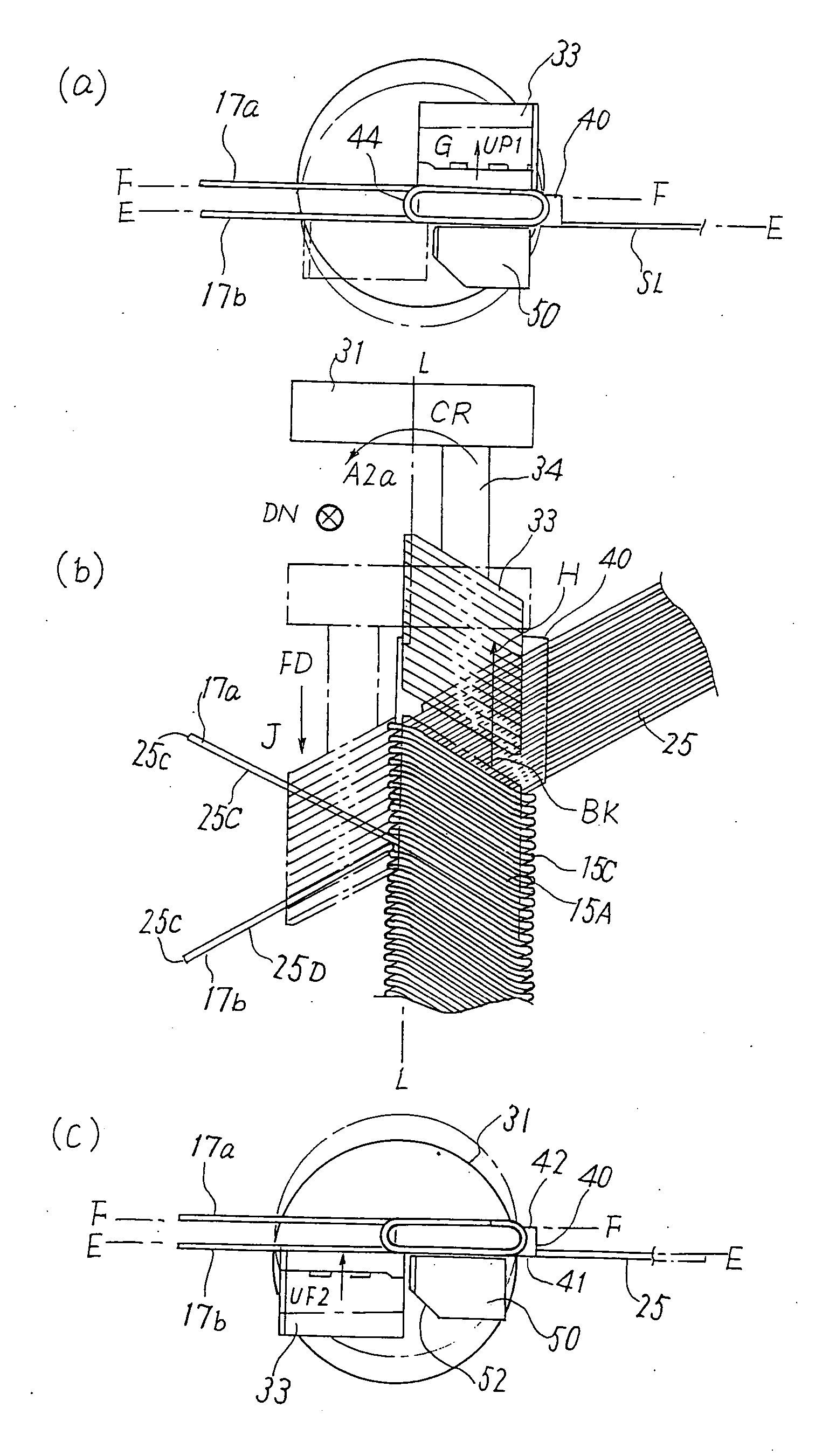
[0112] According to this embodiment 2, a winding step includes a lead wire formation step SLW of forming a lead wire 17a at a set position for a winding member selected from plural winding members wound. This lead wire formation step SLW is carried out by a lead wire preparation step SLP carried out subsequently to an nth first or second wire rod feed step S1 or S3 (n is an arbitrary natural number) and by an nth first or second wire rod turn step S2 or S4 subsequent to this lead wire preparation step SLP. The first or second wire rod turn step S2 or S4 subsequent to this lead wire preparation step SLP is called a lead wire additional formation turn step STL. At the lead wire additional formation turn step STL, the lead wire 17a is formed in addition to a first straight part 15A and a first turn part...
embodiment 3
[0131] Similarly to embodiment 2, embodiment 3 relates to a manufacturing method for a winding assembly of a rotating electrical machine in which a lead wire is formed in a winding step of a winding assembly 10, and is an embodiment in which embodiment 2 is modified and one more lead wire 17b is formed subsequently to one lead wire 17a.
[0132] FIGS. 21(a) and 21(b) show a state in which after one lead wire 17a is formed similarly to embodiment 2, one more lead wire 17b is formed. FIGS. 21(a) and 21(b) show the state in which after the lead wire 17a is formed, the lead wire 17b is formed in the state where the rotation block 33 exists on the second reference surface F-F. Although the state shown in FIGS. 21(a) and 21(b) corresponds to the state shown in FIGS. 18(a) and 18(b) of embodiment 2, the lead wire 17b is additionally formed.
[0133] In the state shown in FIGS. 16(a) and 16(b), the wire rod 25-11 cut at the cut place 25c by the cutting mechanism 70 includes the wire rod portion...
PUM
| Property | Measurement | Unit |
|---|---|---|
| Angle | aaaaa | aaaaa |
| Angle | aaaaa | aaaaa |
| Length | aaaaa | aaaaa |
Abstract
Description
Claims
Application Information
 - R&D
- Intellectual Property
- Life Sciences
- Materials
- Tech Scout
- Unparalleled Data Quality
- Higher Quality Content
- 60% Fewer Hallucinations
Browse by: Latest US Patents, China's latest patents, Technical Efficacy Thesaurus, Application Domain, Technology Topic, Popular Technical Reports.
© 2025 PatSnap. All rights reserved.Legal|Privacy policy|Modern Slavery Act Transparency Statement|Sitemap|About US| Contact US: help@patsnap.com


