System and method for programmable pogo self-piercing riveting

a technology of self-piercing and pogo, which is applied in the field of self-piercing riveting systems and methods, can solve the problems of c-frame support structures that are often too heavy for robotic applications, the rivet gun cannot penetrate fully through the parts, etc., and achieves the effect of convenient alignment of the rivet gun, increasing accessibility and efficiency, and facilitating the driving of the rivet gun

Active Publication Date: 2006-10-19
GM GLOBAL TECH OPERATIONS LLC
View PDF6 Cites 17 Cited by
  • Summary
  • Abstract
  • Description
  • Claims
  • Application Information

AI Technical Summary

Benefits of technology

[0006] The system broadly comprises a rivet gun including a punch; a movable back-up including a plurality of dies; and an alignment subsystem. The rivet gun contacts a first outward side of aligned first and second sheet metal parts, and, using the punch, drives the rivet through the parts. The back-up positions one of the plurality of dies to contact a second outward side of the parts at a location which is substantially directly opposite the contact point of the rivet gun, and both provides a support to facilitate the rivet gun driving the rivet and shapes the projecting end of the fully-penetrated rivet to securely fasten the parts together. The availability of multiple dies increases accessibility and efficiency.
[0007] The alignment subsystem facilitates aligning the rivet gun and back-up opposingly on the outward sides of the parts. The alignment subsystem includes first and second laser-emitting diodes and a plurality of sensors. The first diode is coupled with the rivet gun, and the second diode is coupled with the back-up. The plurality of sensors detect the emissions of the diodes, and, based thereon, adjust or cause to be adjusted, as appropriate, the position of either or both of the rivet gun or the back-up so as to achieve better alignment therebetween.
[0008] The present invention

Problems solved by technology

Unfortunately, this process requires the application of substantial force, typically between 30 kN and 50 kN depending on such factors as the material and thickness of the parts, to cause the rivet to properly penetrate fully through the parts.
Suc

Method used


Image

  • System and method for programmable pogo self-piercing riveting
  • System and method for programmable pogo self-piercing riveting
  • System and method for programmable pogo self-piercing riveting

Examples


Embodiment Construction

).

BRIEF DESCRIPTION OF THE DRAWINGS

[0011] A preferred embodiment of the present invention is described in detail below with reference to the attached drawing figures, wherein:

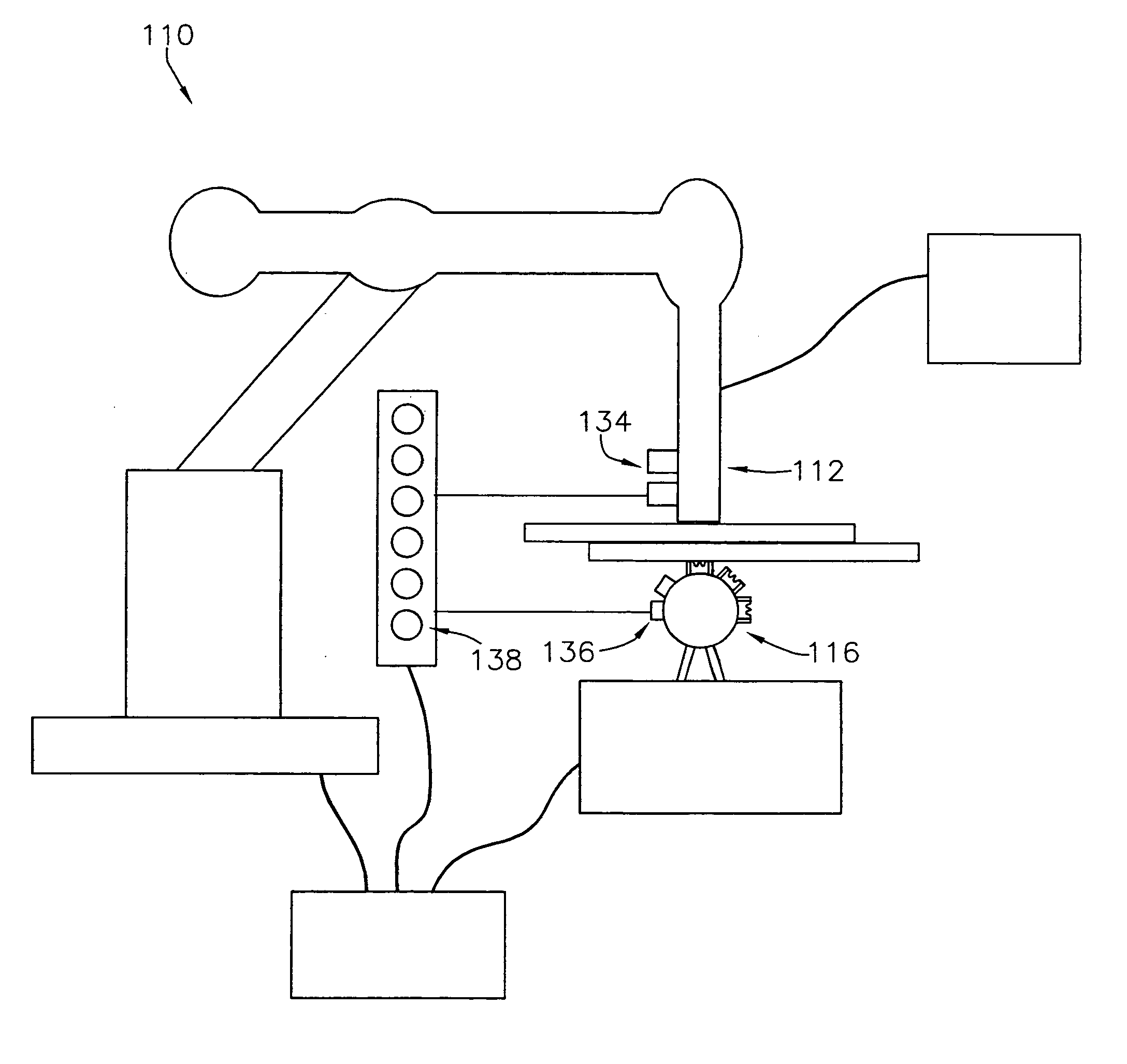
[0012]FIG. 1 is high-level depiction of a preferred embodiment of the system of the present invention;

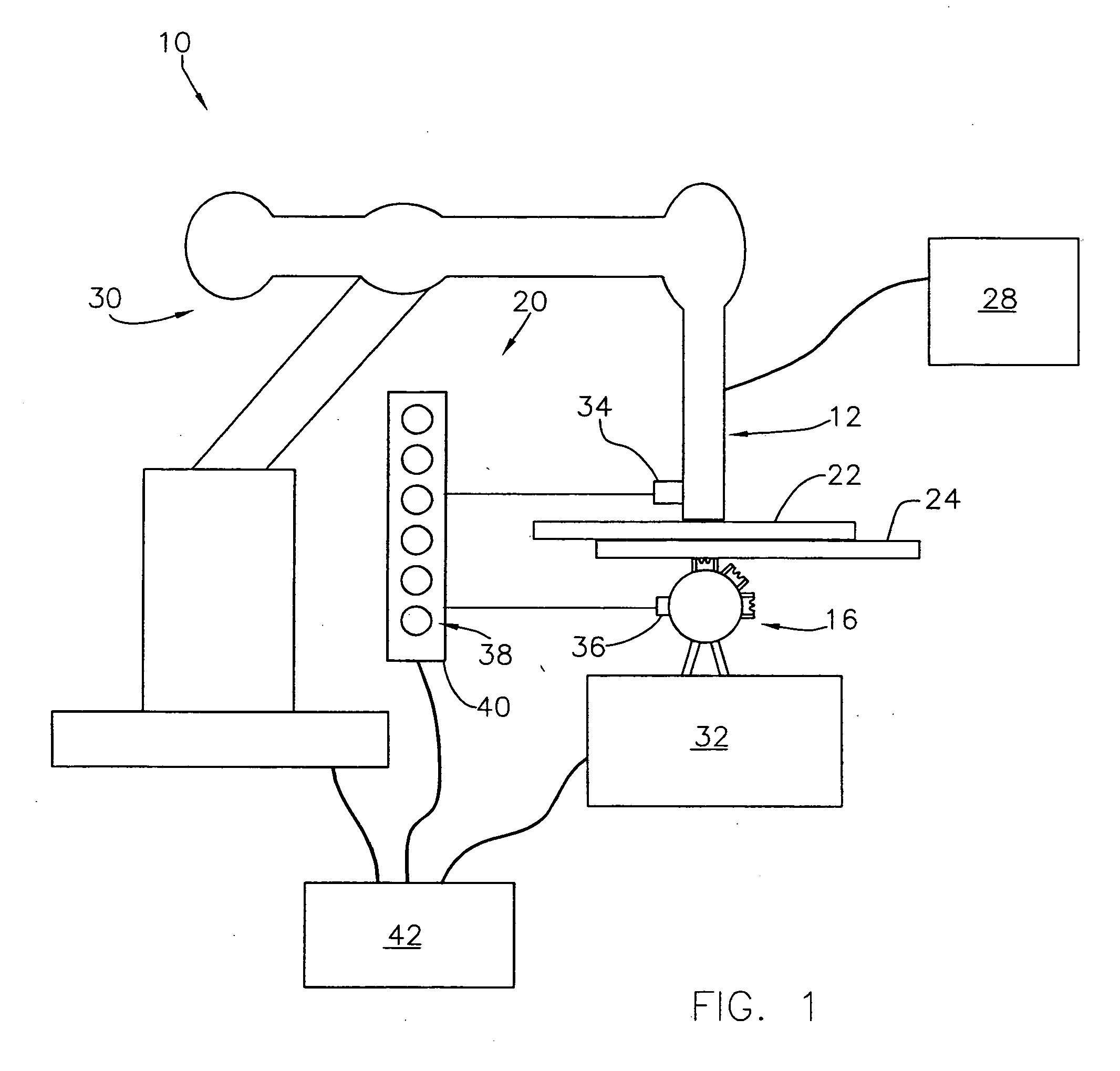
[0013]FIG. 2 is a more detailed depiction of a rivet gun component and a back-up component of the system of FIG. 1;

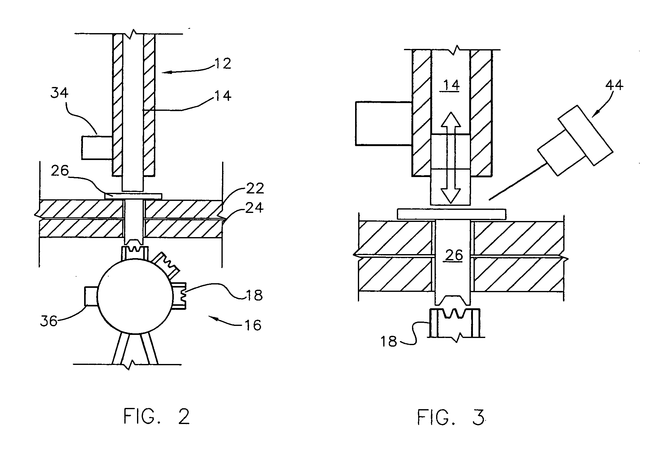
[0014]FIG. 3 is a depiction of a punch component and a die component shown in FIG. 2 employing an oscillation piercing technique of the present invention; and

[0015]FIG. 4 is a high-level depiction of a preferred alternative embodiment of the system of the present invention.

DESCRIPTION OF THE PREFERRED EMBODIMENT

[0016] With reference to the figures, a system and method is herein described, shown, and otherwise disclosed in accordance with the preferred embodiment of the present invention. Broadly, the present invention provides a system and method for improved programmable pogo self-piercing r...


PUM


Abstract

A system and method for self-piercing riveting including an alignment mechanism comprising laser diodes and sensors for facilitating alignment of a rivet gun and a back-up located on opposite sides of sheet metal parts to be joined, and an oscillation piercing technique for reducing force loads on structures, particularly robotic structures, carrying the rivet gun and the back-up.

Description

TECHNICAL FIELD [0001] The present invention relates to systems and methods for self-piercing riveting. More specifically, the present invention concerns a system and method for self-piercing riveting including an alignment mechanism comprising laser diodes and sensors for facilitating alignment of a rivet gun and a back-up located on opposite sides of parts to be joined, and an oscillation piercing technique for reducing force loads on structures, particularly robotic structures, carrying the rivet gun and the back-up. BACKGROUND OF THE INVENTION [0002] Self-piercing riveting (SPR) is a well-known technique used in vehicle assembly as an alternative to resistance spot welding in applications or locations where welding may be difficult or even impossible to accomplish. In programmable pogo SPR, a rivet gun and a die move together, with one being substantially directly opposite the other, over opposite surfaces of two aligned sheet metal parts to a series of rivet locations. At each ...

Claims


Application Information

Patent Timeline
IPC IPC(8): B23P19/00B23P21/00
CPCB21J15/025B21J15/08B21J15/12B21J15/28B21J15/36Y10T29/49956Y10T29/53013Y10T29/53043Y10T29/5377Y10T29/5343Y10T29/5307
Inventor WANG, PEI-CHUNGSUN, PETER C.STEVENSON, ROBINWAMPLER, CHARLES W. II
Owner GM GLOBAL TECH OPERATIONS LLC
Why Eureka
Try Eureka