Pneumatic shock absorber with an ancillary air chamber

Inactive Publication Date: 2006-10-19
APROTECH
View PDF4 Cites 30 Cited by
  • Summary
  • Abstract
  • Description
  • Claims
  • Application Information

AI Technical Summary

Benefits of technology

[0008] Based on this innovative design of present invention, when extensible axle of pneumatic shock absorber starts to shrink, the effective flexible travel can be extended in tune with the volume change of ancillary air chamber. The comparative schematic drawing between pressure curve LI of

Problems solved by technology

Yet, no continued compression could be performed when gas is compressed in a single enclosure to some extent, namely, a turning point will be visibly formed at rear section of the compression curve, from which the travel requires a sharp escalating compressive force.
Therefore,

Method used


Image

  • Pneumatic shock absorber with an ancillary air chamber
  • Pneumatic shock absorber with an ancillary air chamber
  • Pneumatic shock absorber with an ancillary air chamber

Examples


Embodiment Construction

[0017] The features and the advantages ofthe present invention will be more readily understood upon a thoughtful deliberation of the following detailed description of a preferred embodiment of the present invention with reference to the accompanying drawings.

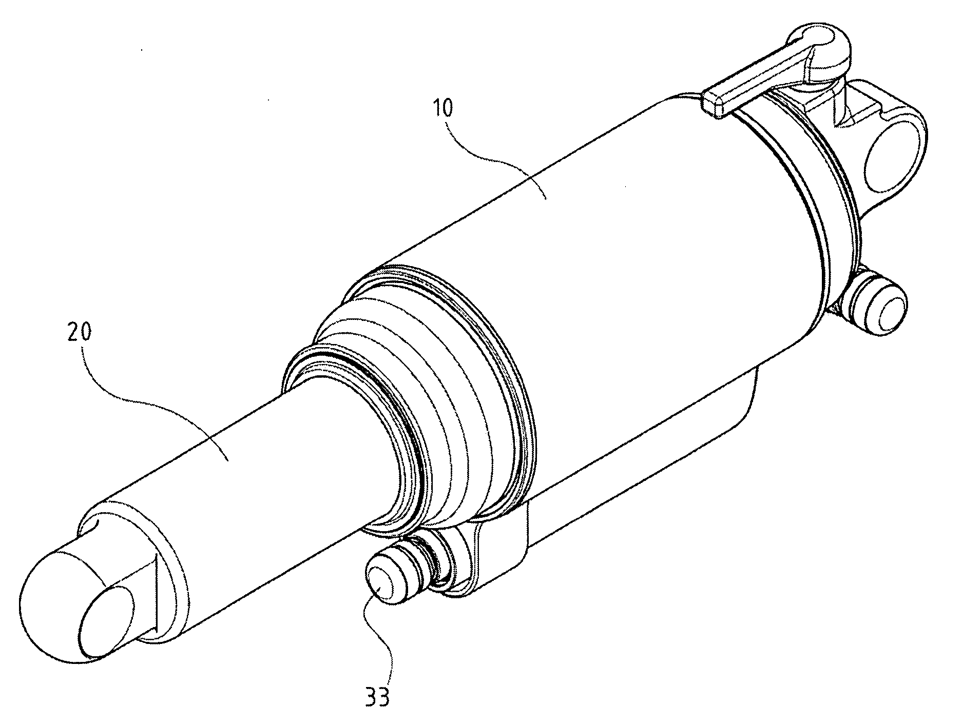
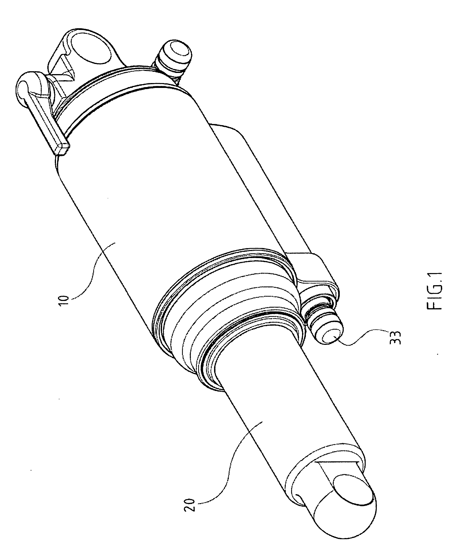
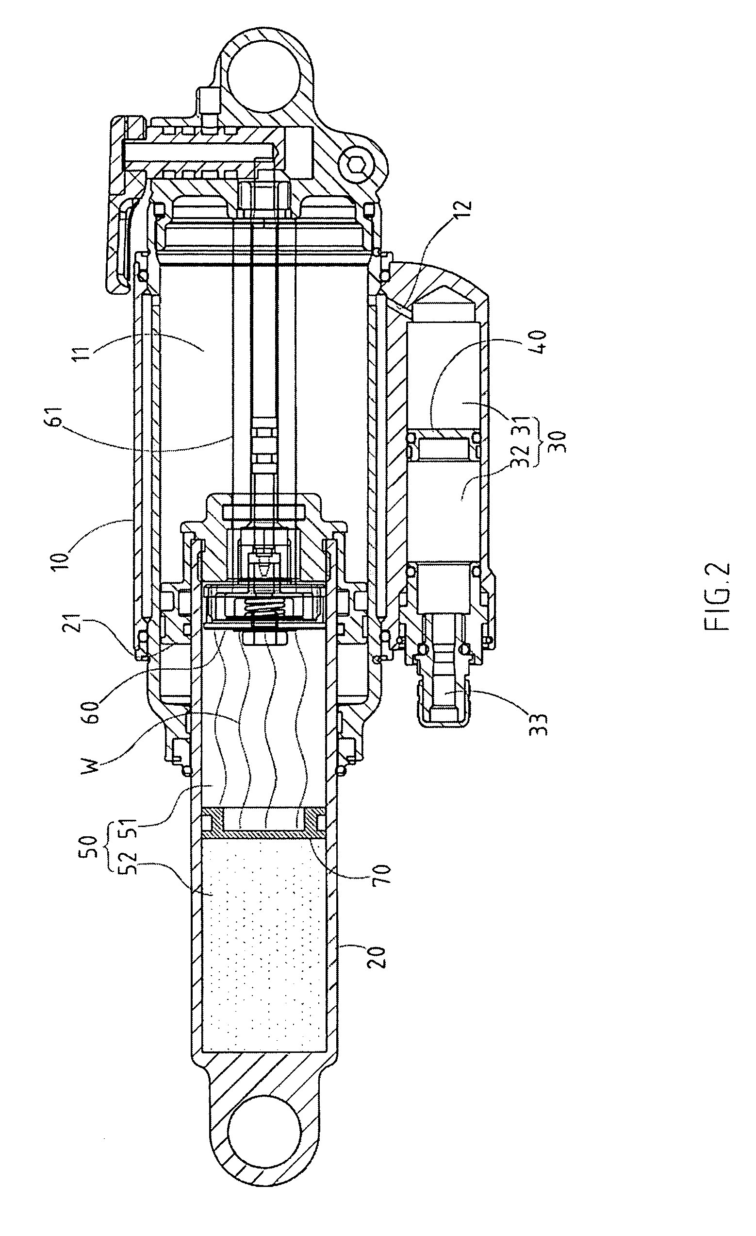
[0018] As shown in FIGS. 1-3, a pneumatic shock absorber with an ancillary air chamber embodied in the present invention comprises: [0019] a cylinder body 10, with a hollow air chamber 11; [0020] an extensible axle 20, which can slide by combining a piston 21 with air chamber 11 of cylinder body 10; [0021] at least a first ancillary air chamber 30, which is installed at one side of cylinder body 10, but separated from its air chamber 11 and interconnected via a gas vent 12; [0022] a first floating piston 40 mounted into first ancillary air chamber 30, which is used to divide first ancillary air chamber 30 into an internal air chamber 31 and an external air chamber 32; [0023] at least a second ancillary air chamber 50, which is ...


PUM


Abstract

The present ilylltivllj provides-a pneumatic shock absorber fitted with an ancillary air chamber. The miajor fatuire of such know-how is that pneumatic shock absorber is fitted with an ancillary air chamber interconnected to or separated from air chamber of cylinder body. And, a floating piston is mounted into the ancillary air chamber. Based on this imiiovative design when When the extensible axle of pneumatic shock absorber starts to shrink, the effective flexible travel can be extended in tune with the volume change of ancillary air chamber, thereby meeting actual demands of drivers.

Description

RELATED U.S. APPLICATIONS [0001] Not applicable. STATEMENT REGARDING FEDERALLY SPONSORED RESEARCH OR DEVELOPMENT [0002] Not applicable. REFERENCE TO MICROFICHE APPENDIX [0003] Not applicable. FIELD OF THE INVENTION [0004] The present invention relates generally to a pneumatic shock absorber, and more particularly to a pneumatic shock absorber which is designed with an ancillary air chamber linked to the cylinder body's air chamber. BACKGROUND OF THE INVENTION [0005] Generally, the conventional pneumatic shock absorber is characterized by compressible high-pressure gas instead of conventional spring members, thereby offering the same flexibility for its extensible axle under stress. Yet, no continued compression could be performed when gas is compressed in a single enclosure to some extent, namely, a turning point will be visibly formed at rear section of the compression curve, from which the travel requires a sharp escalating compressive force. Therefore, conventional pneumatic shoc...

Claims


Application Information

Patent Timeline
IPC IPC(8): F16F9/00
CPCF16F9/0209
Inventor CHEN, MENG-ZONG
Owner APROTECH
Why Eureka
Try Eureka