Paper towel holder and dispenser

Inactive Publication Date: 2006-10-19
WARDELL JANICE W
View PDF17 Cites 6 Cited by
  • Summary
  • Abstract
  • Description
  • Claims
  • Application Information

AI Technical Summary

Benefits of technology

[0010] The apparatus of the invention has the advantage of being low in cost.
[0011] The apparatus of the invention has the additional advantage of being easily connectabl

Problems solved by technology

Such placement takes up sp

Method used


Image

  • Paper towel holder and dispenser
  • Paper towel holder and dispenser
  • Paper towel holder and dispenser

Examples


Example

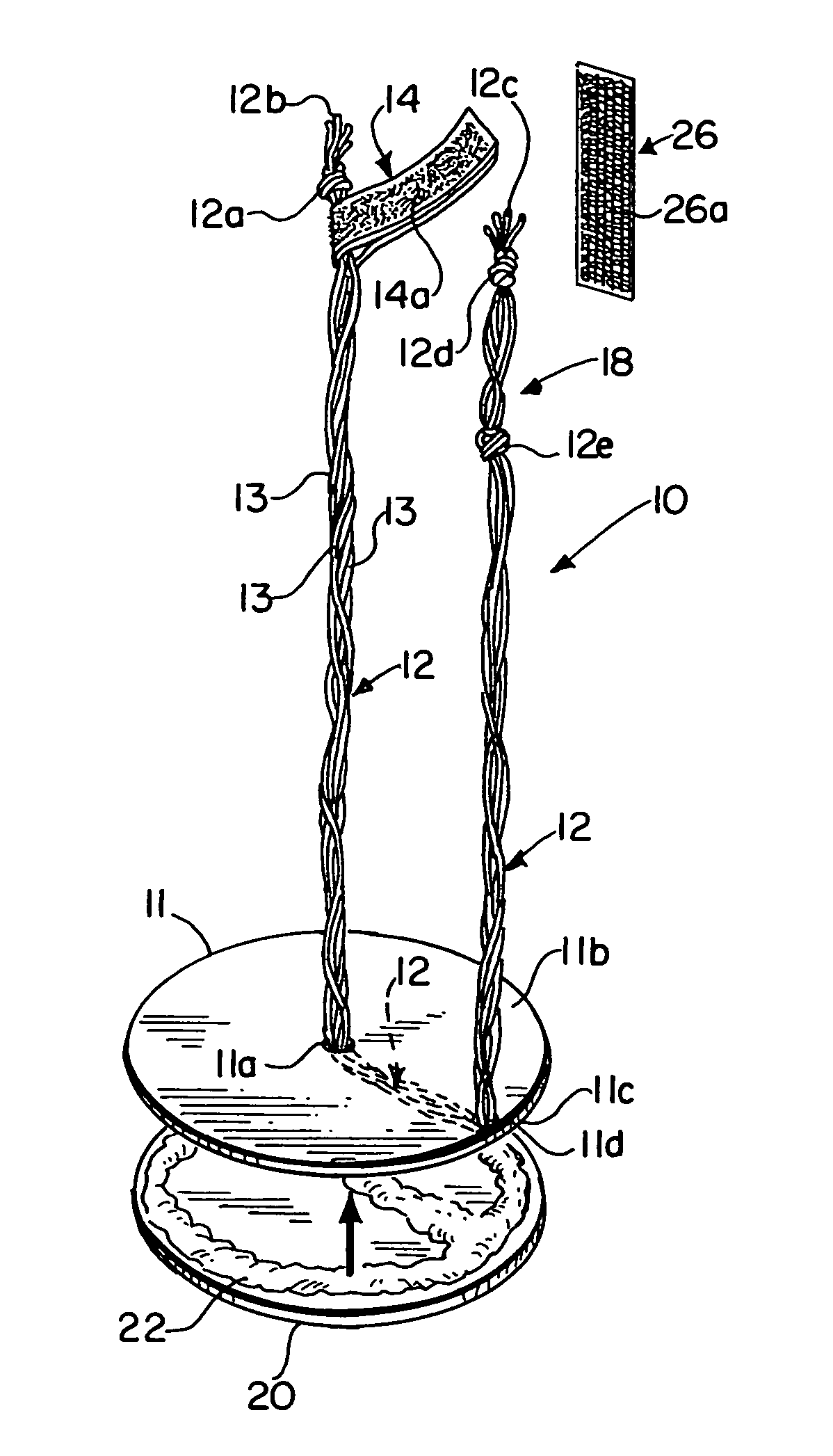
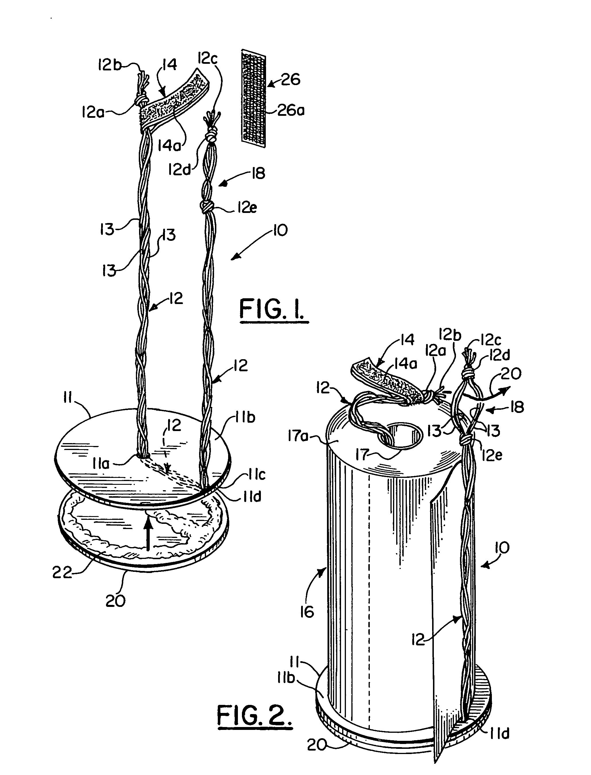
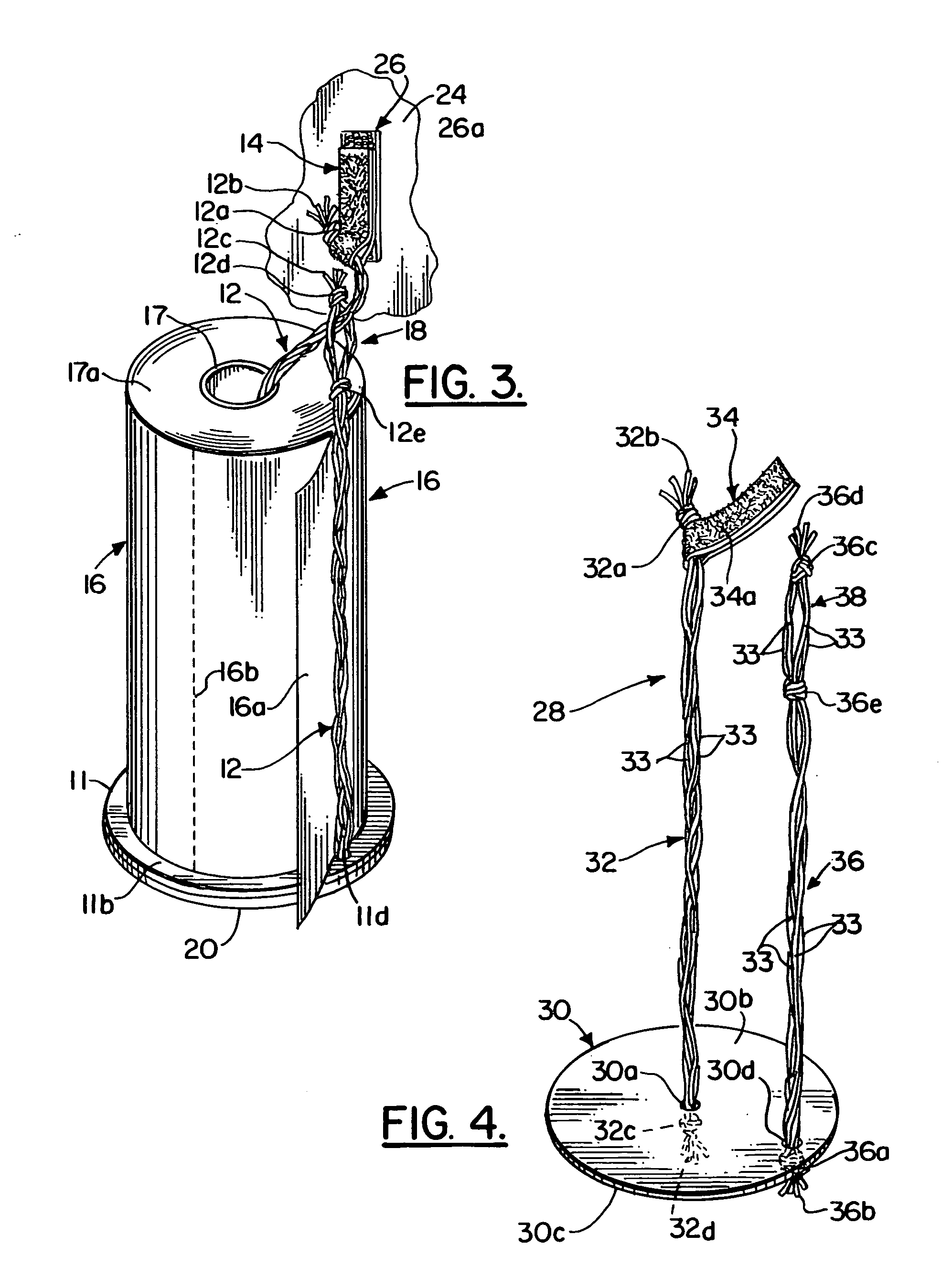
[0017] Referring now to the drawings, and in particular to FIGS. 1-3, the paper towel holder of the invention is generally indicated by the numeral 10. The paper towel holder and dispenser of the invention has a circular base plate 11. Circular base plate 11 is a flat circular disc constructed from a rigid material. The rigid materials from which circular base plate 11 may be constructed include polymeric materials commonly known in the art as plastics, cardboard, metal, or the like.

[0018] Circular base plate 11 has a circular opening 11a in the center thereof which extends completely through circular base plate 11 from the top side 11b of circular base plate 11 to the bottom side 11c of circular base 11. A flexible string or cord generally indicated by the numeral 12 extends through circular opening 11a in circular base plate 11. Cord 12 is preferably formed from a plurality of decorative strings 13 as shown in the drawings. Preferably, as shown in FIG. 2, there are four strings i...


PUM


Abstract

A paper towel holder and dispenser including a flat circular base plate having a top side and a bottom side with a first opening in the center thereof and a second opening near the outer edge thereof, a first cord extending upward from the bottom side of the base plate through the first opening and through the hollow central core of a roll of paper towels, a strip of hook and loop material connected to the upper end of the first cord, a second cord extending upward from the bottom side of the base plate through the second opening and around the outer surface of a roll of paper towels, and a loop connected to the second cord on the upper end of the second cord, the loop being adapted to receive the strip of hook and loop material connected to the upper portion of the first cord extending out of the end of the central hollow core.

Description

BACKGROUND OF THE INVENTION [0001] 1. Field of the Invention [0002] The present invention relates to apparatus for holding a roll of paper towels. In particular, the invention relates to apparatus for holding and dispensing paper towels. [0003] 2. Description of the Related Art [0004] A typical commercially available roll of paper towels is cylindrical in shape and has a central hollow cylindrical core former of paperboard or cardboard. Paper toweling is wound continuously around the hollow cylindrical core. Usually the toweling is provided with repetitive, spaced-apart lines of perforations to form lines of weakness to enable individual sheets or towels to be separated from the roll. [0005] Paper towels are widely used throughout the world. Many homes have paper towel holding and dispensing devices permanently attached to the kitchen walls and cabinets. Such devices are commonly attached to the walls and cabinets of the kitchen of a home with screws or bolts. [0006] Travelers frequ...

Claims


Application Information

Patent Timeline
IPC IPC(8): B65H16/04
CPCA47K10/3836A47K10/3818
Inventor WARDELL, JANICE W.
Owner WARDELL JANICE W
Why Eureka
Try Eureka