Modular permanent magnet chuck

a permanent magnet chuck and module technology, applied in the field of modules, can solve the problems of large surface contact area, large volume of magnetic chucks, and low attractive force of magnet chucks, and achieve the effect of maximizing the magnitude of attractive magnetic force, reducing the “short-circuiting” of magnetic flux, and high magnetic flux in the workpi

Active Publication Date: 2006-10-19
GM GLOBAL TECH OPERATIONS LLC
View PDF7 Cites 25 Cited by
  • Summary
  • Abstract
  • Description
  • Claims
  • Application Information

AI Technical Summary

Benefits of technology

[0006] A chuck assembly includes two complementary (preferably matching) chuck layers placed in face to face (overlying / underlying) arrangement with the edges of the permanent magnet pieces aligned and the soft magnet blocks aligned. The facing edges of the permanent magnets in the facing chuck layers are separated by strips of non-magnetic material to minimize short circuiting of magnetic flux between permanent magnets.
[0008] The relatively thin permanent magnet bodies (sheets or plates) are made of any suitable permanent magnet material such as neodymium-iron-boron compositions, rare earth element-cobalt compositions, hard ferrite compositions, or the like. Magnetically soft iron and / or magnetically soft alloys of iron-silicon, nickel-iron and soft ferrites are suitable for use as flux carriers between the magnet blocks. Brass or other non-magnetic materials are placed between the central edges of the permanent magnet bodies in each chuck layer and at facing edges of permanent magnet bodies between chuck layers to minimize “short-circuiting” of magnetic flux between permanent magnets.
[0009] The use of complementary or matching chuck layers of alternating thin permanent pieces and larger soft magnet blocks enables the concentration of a high level of magnetic flux in a workpiece. The flux is concentrated in a clutch face most of which is soft magnet material. The magnitude of attractive magnetic force appears to be maximized with respect to the inherent magnetic properties of the permanent magnet and soft magnet pieces. This chuck architecture permits the use of smaller structures, or lower-in-height structures, for a given chuck application. And, as stated, when the chuck layers and working face of the device are oriented horizontally, a chuck layer can be positioned or rotated for magnetic activation from the top or bottom of the chuck.

Problems solved by technology

These permanent magnet chucks usually have relatively low levels of attractive force and their load carrying capacities are somewhat limited.
Consequently, the magnetic chucks are very bulky in their physical dimensions and have large surface contact areas in order to meet their performance targets.
These conditions pose physical obstructions in many practical workplace applications where there is not room for the sweeping reach of such a side-located lever.

Method used


Image

  • Modular permanent magnet chuck
  • Modular permanent magnet chuck
  • Modular permanent magnet chuck

Examples


Embodiment Construction

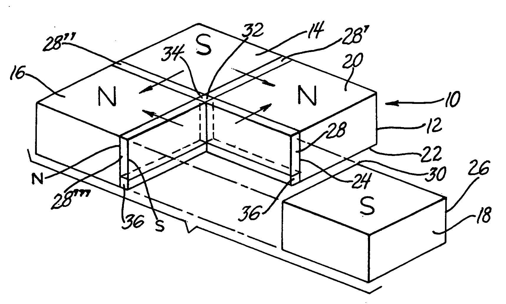
[0022] This invention provides a design for a compact, modular, two layer permanent magnet chuck. The arrangement of relatively thin permanent magnet pieces between larger soft magnet blocks in cooperatively matching layers of the chuck results in a compact device that provides a high magnetic flux per unit volume of the chuck. In other words, lower or smaller chucks can be used in a workpiece lifting or holding application.

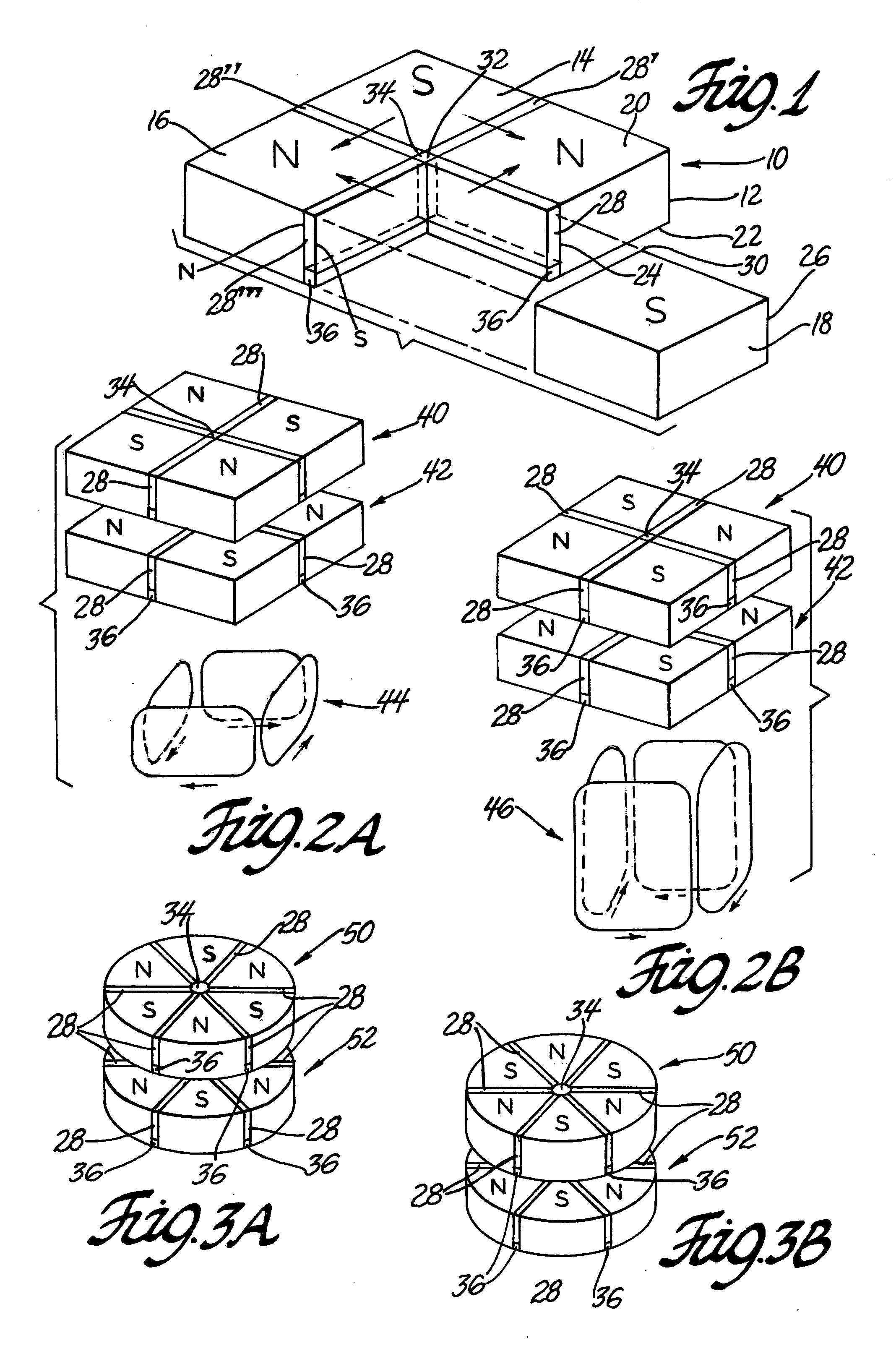
[0023] The modular chuck comprises two geometrically similar or identical layers of identical or interchangeable permanent magnet and soft magnet members. FIGS. 1 and 2A and 2B illustrate an embodiment of the invention in which four identical square soft magnet blocks are used in each layer of the chuck assembly. In FIG. 1, one clutch layer 10 comprises four identical square soft magnet blocks 12, 14, 16 and 18 with flat top 20 and bottom 22 surfaces (indicted only on block 12 for simplicity of illustration). As stated above, soft magnet block 18 is pulled out o...


PUM

PropertyMeasurementUnit
rotationaaaaaaaaaa
rotationaaaaaaaaaa
anglesaaaaaaaaaa

Abstract

A permanent magnet chuck for holding or lifting workpieces is formed of two overlying / underlying flat surfaced chuck layers having a common center of rotation. In each chuck layer an even number of permanent magnet plates radiate from the center of rotation at equal angles with blocks of magnetically soft material between them. The permanent magnet plates are magnetized so that the interposed soft magnet blocks exhibit alternating N-S magnetic polarities. The organization of the permanent magnet plates and soft magnet bodies is matching and complementary so that relative rotation of the chuck layers magnetically activates or de-activates the chuck.

Description

TECHNICAL FIELD [0001] This invention pertains to modular permanent magnet chucks. More specifically, this invention pertains to a magnetic chuck comprising two layers of permanent magnet sheets or plates interposed with larger soft magnet blocks. Each layer contains an even number of similarly shaped permanent and soft magnet bodies, and one chuck layer is rotated with respect to the other to convert the chuck from a magnetically inactive state to an active state for holding workpieces. BACKGROUND OF THE INVENTION [0002] Manually activated permanent magnet chucks have been in existence for many years. One of the common applications is as a work-holding device used in machining operations on grinders, lathes, and mills. Another application is a mechanical lifter for material handling purposes. These permanent magnet chucks usually have relatively low levels of attractive force and their load carrying capacities are somewhat limited. Consequently, the magnetic chucks are very bulky i...

Claims


Application Information

Patent Timeline
Patent Type & Authority Applications(United States)
IPC IPC(8): H01F7/20
CPCB23Q3/152B23Q3/1546H01F7/0252
Inventor SHEN, CHI-HUNG
Owner GM GLOBAL TECH OPERATIONS LLC
Why Eureka
Try Eureka